
F 450 4WD Super Duty V10-6.8L VIN D (2004)
Power Take-Off: Description and Operation
POWER TAKE-OFF SWITCH AND CIRCUIT
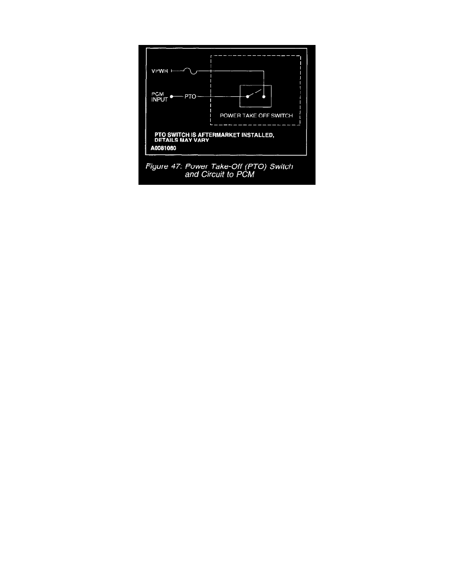
Power Take-Off (PTO) Switch And Circuit To PCM
The Power Take-Off (PTO) circuit (Figure 47) is used by the PCM to disable some of the OBD II Monitors during PTO operation. The PTO switch is
normally open. When the PTO unit is activated the PTO switch is closed and battery voltage is supplied to the PTO input circuit. This indicates to the
PCM that an additional load is being applied to the engine.
When the PTO unit is activated, the PCM disables some OBD-II monitors, which may not function reliably during PTO operation. Without the PTO
circuit information to the PCM, false Diagnostic Trouble Codes (DTCs) may be set during PTO operation. Prior to an Inspection/Maintenance test, the
vehicle will have to be operated with the PTO disengaged long enough to successfully complete the OBD-II Monitors.