
F 450 4WD Super Duty V10-6.8L VIN Z CNG (2003)
Alternator: Testing and Inspection
Generator Testing
Dual Generators
CAUTION:
^
To prevent damage to the Generator (GEN), do not make jumper wire connections except as directed.
^
Do not allow any metal object to come in contact with the housing and the internal diode cooling fins with key on or off. A short circuit will result
and burn out the diodes.
NOTE:
^
Battery posts and cable clamps must be clean and tight for accurate meter indications.
^
Refer to the battery tester manual for complete directions on checking out the charging system.
1. Turn OFF all lamps and electrical components.
2. Place the vehicle in transmission range NEUTRAL and apply the parking brake.
3. Carry out Load Test and No-Load Test according to the following component tests.
Generator On-Vehicle Test - Load Test
1. Switch the tester to the ammeter function.
2. Connect the positive and negative leads of the tester to the corresponding battery terminals.
3. Connect the current probe to the generator B+ output lead, Circuit 36 (YE/WH).
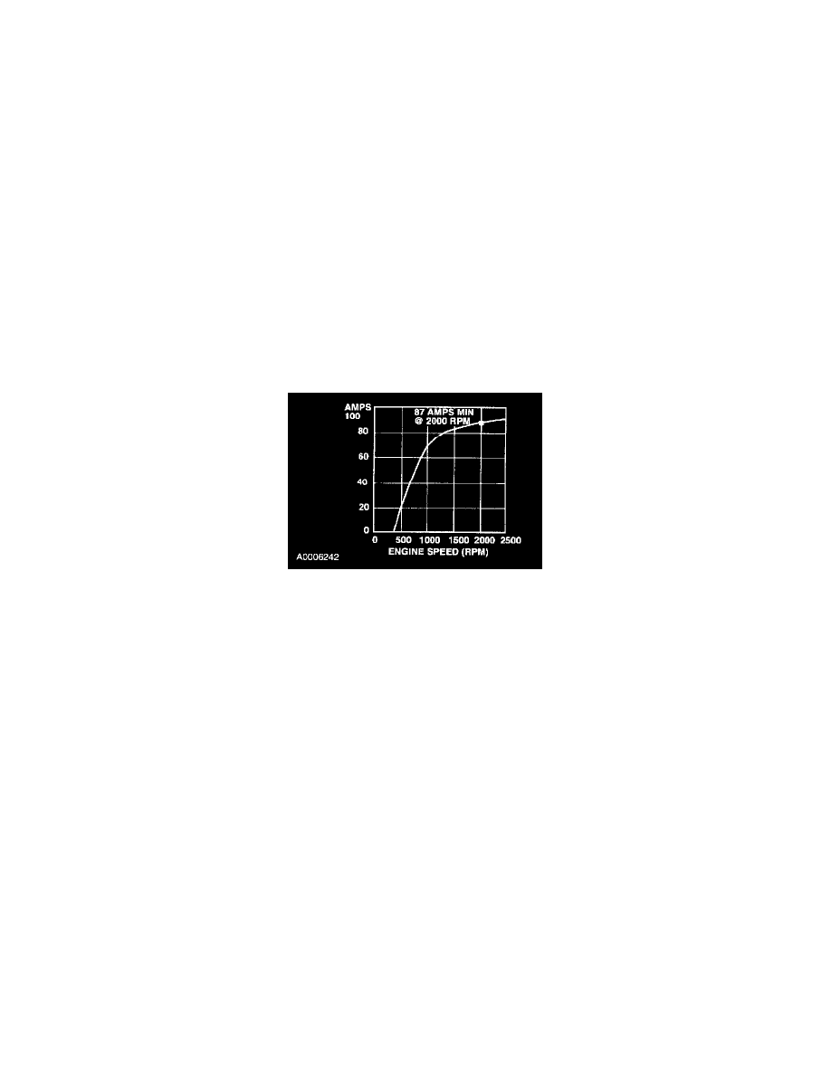
130 Amp Generator
4. With the engine running at 2,000 rpm, adjust the tester load bank to determine the output of the generator. Refer to the symptom chart for
diagnostic procedures. See: Testing and Inspection/With Dual Generators/Diagnosis By Symptom
NOTE: Make certain to disconnect the generator that is not being tested.
5. With the engine running, turn the A/C on, if equipped, the blower motor on high speed and the headlamps on high beam.
6. Increase the engine speed to approximately 2,000 rpm. The voltage should increase a minimum of 0.5 volt above the base voltage.
^
Backprobe the I circuit at the generator connector (connector plugged in) and measure the I circuit voltage. If the voltage is less than 2 volts,
install a new generator.
^
If the voltage does not increase as specified, carry out the Generator On-Vehicle Tests.
^
If the voltage increases as specified, the charging system is operating normally. Proceed to the following battery tests.
Generator On-Vehicle Test - No-Load Test
1. Switch the tester to the voltmeter function.
2. Connect the voltmeter positive lead to the generator B+ terminal and the negative lead to ground.
3. Turn all electrical accessories off.
4. With the engine running at 2,000 rpm, check the generator output voltage. The voltage should be between 13.0 and 15.5 volts. If not, refer to the
pinpoint test or to the Symptom Chart for diagnostic procedures. See: Testing and Inspection/With Dual Generators/Pinpoint Tests See: Testing
and Inspection/With Dual Generators/Diagnosis By Symptom
Single Generator
CAUTION:
^
To prevent damage to the generator, do not make jumper wire connections except as directed.
^
Do not allow any metal object to come in contact with the housing and the internal diode cooling fins with key on or off. A short circuit will result
and burn out the diodes.
NOTE: