
F 450 4WD Super Duty V8-6.4L DSL Turbo (2008)
8. Install interim 0 degree service adjusters to both sides of the vehicle.
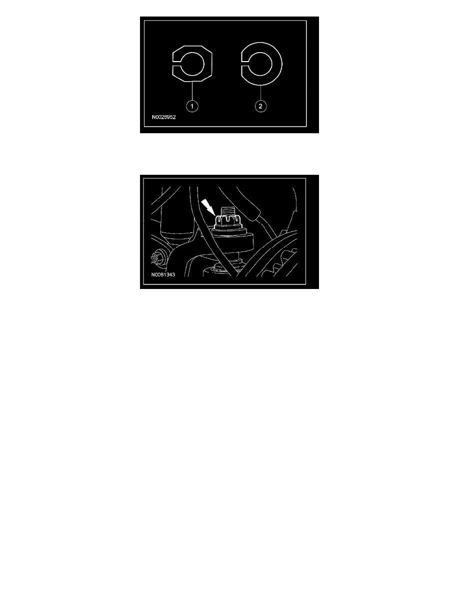
9. Install the nut onto the upper ball joint.
^
Tighten to 94 Nm (69 ft. lbs.).
10. Install the front wheel(s) and check the caster and camber readings with the 0 degree service adjusters installed.
11. Calculate the maximum amount of camber and/or caster adjustment required to achieve the optimal settings, as provided in the Alignment
Specifications table, by subtracting the measured values from the optimal target values.
Example: For a four wheel drive (4WD) F-350 pickup with single rear wheels (SRW),
^
Optimal camber spec target = 0.15 ± 0.75.
^
Optimal LH caster spec target = 2.7 ± 1.2.
^
Measured camber = 1.2 (out-of-spec).
^
Measured LH caster = 2.0 (within spec).
^
Required camber adjustment = 0.15 - 1.2 = -0.9.
^
Preferred caster adjustment = 2.7 - 2.0 = +0.7, however not required.
12. Using the Camber/Caster Service Adjuster table, determine the appropriate replacement service adjuster needed to correct alignment. There is
usually more than one combination of service adjuster and orientation that can be chosen to achieve alignment measurements within specifications.
If a compromise is required, choose the adjuster and orientation which optimizes the camber value and maximizes the caster value.
Example: continuing the above example,
^
Choose an adjuster with a 1 degree adjustment circle.
^
Set the adjuster to the 180 degree position to achieve a -1 degree camber and 0 degree caster shift setting.