
F 450 4WD Super Duty V8-7.3L DSL Turbo VIN F (2001)
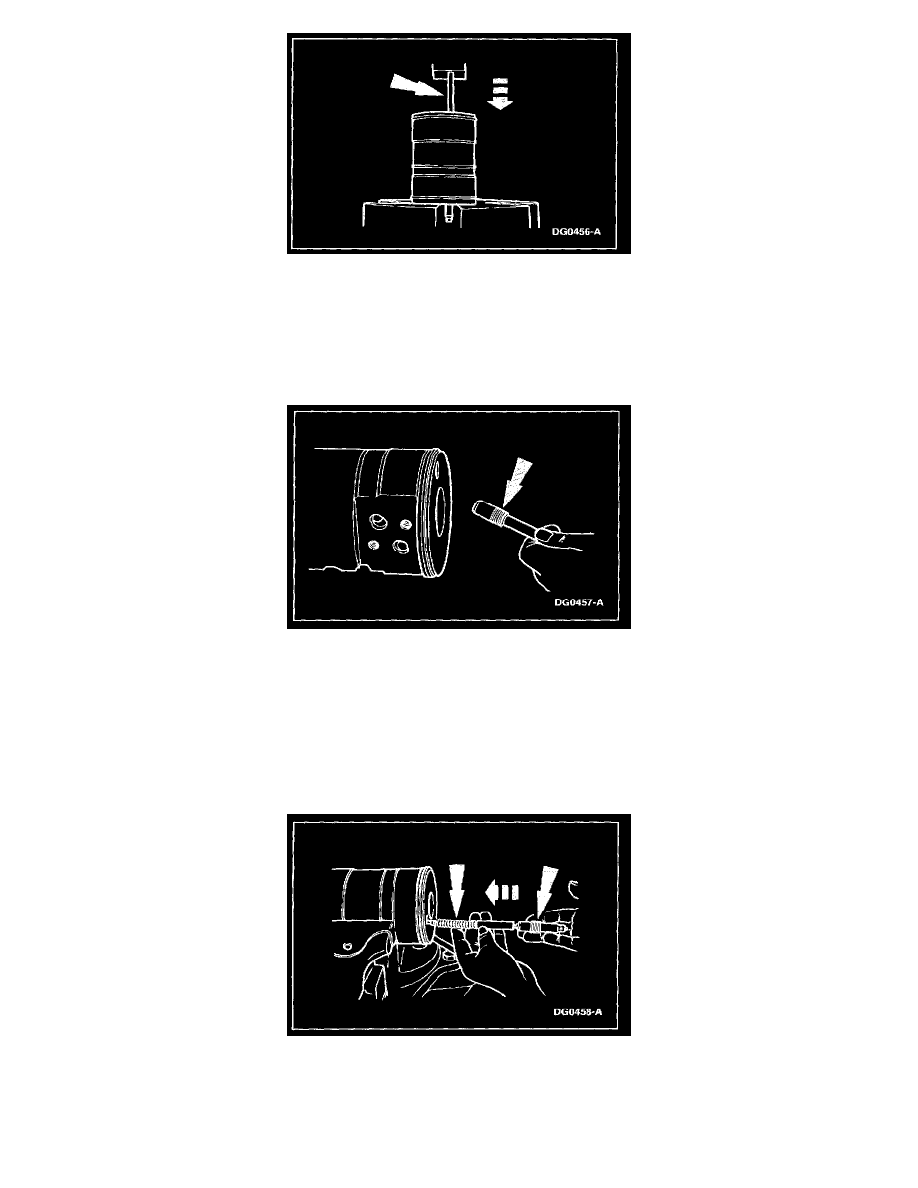
2. NOTE: If one poppet seat and sleeve assembly was left in the rack piston, it can be reset for automatic poppet adjustment by inserting a 9.52-mm
(3/8-inch) diameter x 152.4-mm (6-inch) drill rod down through the poppet seat hole at the opposite end of the rack piston and against the
adjuster seat to press the seat in until it bottoms against the adjuster sleeve.
Press the adjuster seat into the sleeve using 2,224-11,120 N (500-2500 lb) force until the shoulder on the seat bottoms against the sleeve and
remove the adjuster seat and sleeve assembly from the rack pinion.
-
Repeat the procedure for the other poppet seat and sleeve assembly if removed.
3. CAUTION: Do not allow Loctite(R) or Locquic to get on the adjuster seat and sleeve assembly. The poppet will not function correctly.
Carefully apply Locquic T primer to the threads in the poppet holes and threads on the seat and sleeve assemblies. Allow to dry for ten minutes,
then carefully apply Loctite(R) RC680 to the same threads.
4. WARNING: Wear eye protection while assembling poppets, as spring-loaded poppets can eject and cause eye injury.
Place the rack piston in a soft-jawed vice and turn one poppet adjuster seat and sleeve assembly (slotted end out) into the poppet hole in one end of
the rack piston.
5. From the other end of the poppet hole in the rack piston, install the following:
-
one poppet
-
poppet spring
-
nylon spacer rod
-
push tube