
F 550 2WD Super Duty V10-6.8L (2009)
-
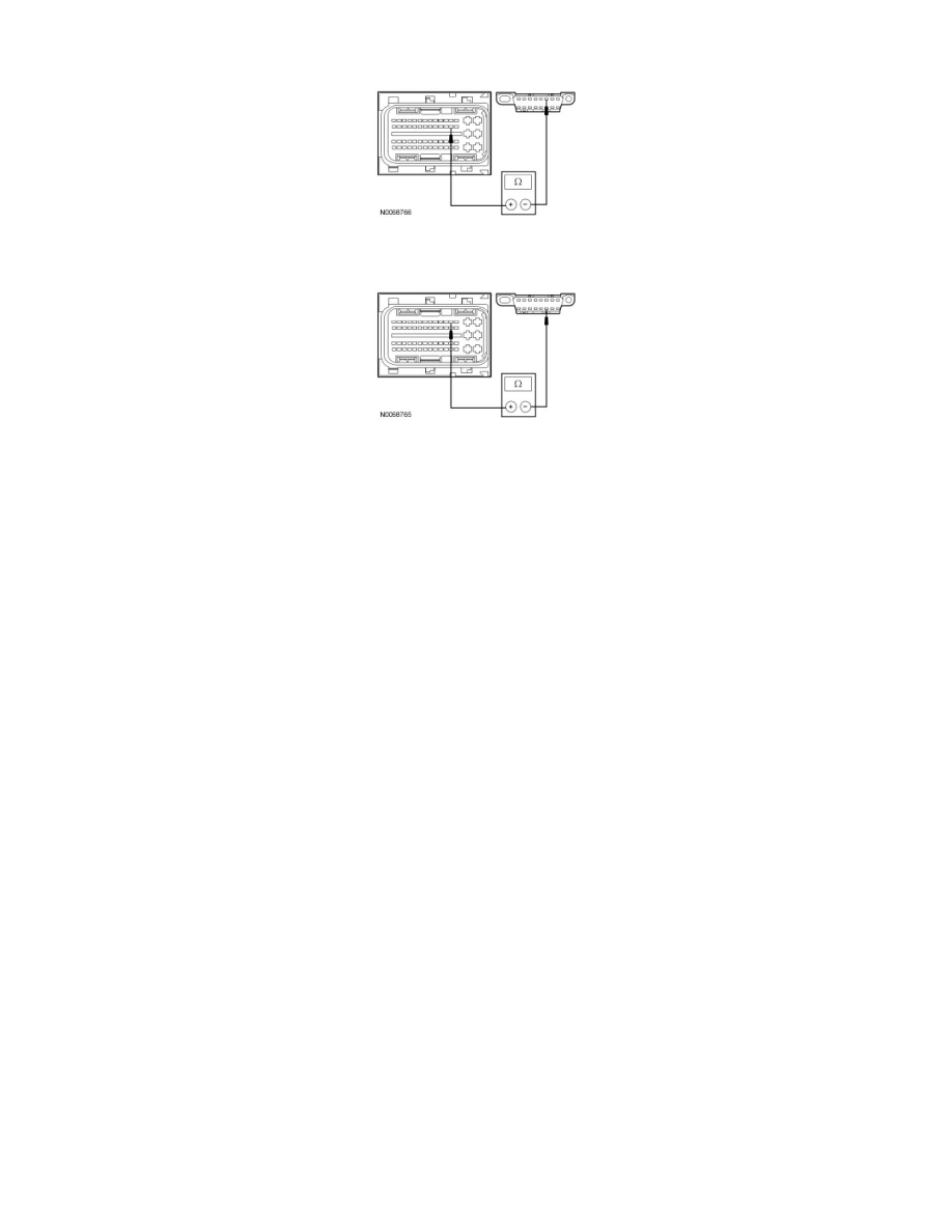
For diesel engines, measure the resistance between the PCM C1232b-34, circuit VDB04 (WH/BU), harness side and the DLC C251-6, circuit
VDB04 (WH/BU), harness side.
-
For diesel engines, measure the resistance between the PCM C1232b-47, circuit VDB05 (WH), harness side and the DLC C251-14, circuit
VDB05 (WH), harness side.
-
Are the resistances less than 5 ohms?
Yes
CONNECT the negative battery cable. GO to A5.
No
REPAIR the circuit in question. CONNECT the negative battery cable. CLEAR the DTCs. REPEAT the network test with the scan tool.
-------------------------------------------------
A5 CHECK FOR CORRECT PCM OPERATION
-
Disconnect all the PCM connectors.
-
Check for:
-
corrosion
-
damaged pins
-
pushed-out pins
-
Connect all the PCM connectors and make sure they seat correctly.
-
Operate the system and verify the concern is still present.
-
Is the concern still present?
Yes
INSTALL a new PCM. REFER to Computers and Control Systems Information. CLEAR the DTCs. REPEAT the network test with the scan tool.
No
The system is operating correctly at this time. The concern may have been caused by a loose or corroded connector. CLEAR the DTCs. REPEAT the
network test with the scan tool.
-------------------------------------------------
Pinpoint Test B: The ABS Module Does Not Respond To The Scan Tool
Communications Network
Pinpoint Tests
Pinpoint Test B: The ABS Module Does Not Respond To The Scan Tool
Refer to Wiring Diagram Set 14, Module Communications Network for schematic and connector information. See: Diagrams/Electrical