
Testing and Inspection of Information Bus Component in a 2009 F 550 2WD Super Duty
INSTALL a new SJB. CLEAR the DTCs. REPEAT the network test with the scan tool.
No
The system is operating correctly at this time. The concern may have been caused by a loose or corroded connector. CLEAR the DTCs. REPEAT the
network test with the scan tool.
-------------------------------------------------
Pinpoint Test I: The Driver Seat Module (DSM) Does Not Communicate With The Scan Tool
Communications Network
Pinpoint Tests
Pinpoint Test I: The Driver Seat Module (DSM) Does Not Communicate With the Scan Tool
Normal Operation
The Driver Seat Module (DSM) is optional equipment. The DSM communicates with the scan tool through the Medium Speed Controller Area Network
(MS-CAN). Circuits VDB06 (GY/OG) (MS-CAN +) and VDB07 (VT/OG) (MS-CAN -) provide the network connection to the DSM. Voltage for the
DSM is provided by circuits SBP12 (GN/RD) and SBB45 (GY/RD). Circuits GD133 (BK) and GD179 (BK/VT) provide ground.
This pinpoint test is intended to diagnose the following:
-
Fuse
-
Wiring, terminals or connectors
-
DSM
PINPOINT TEST I: THE DSM DOES NOT RESPOND TO THE SCAN TOOL
NOTICE: Use the correct probe adapter(s) when making measurements. Failure to use the correct probe adapter(s) may damage the
connector.
NOTE: Failure to disconnect the battery when instructed will result in false resistance readings.
-------------------------------------------------
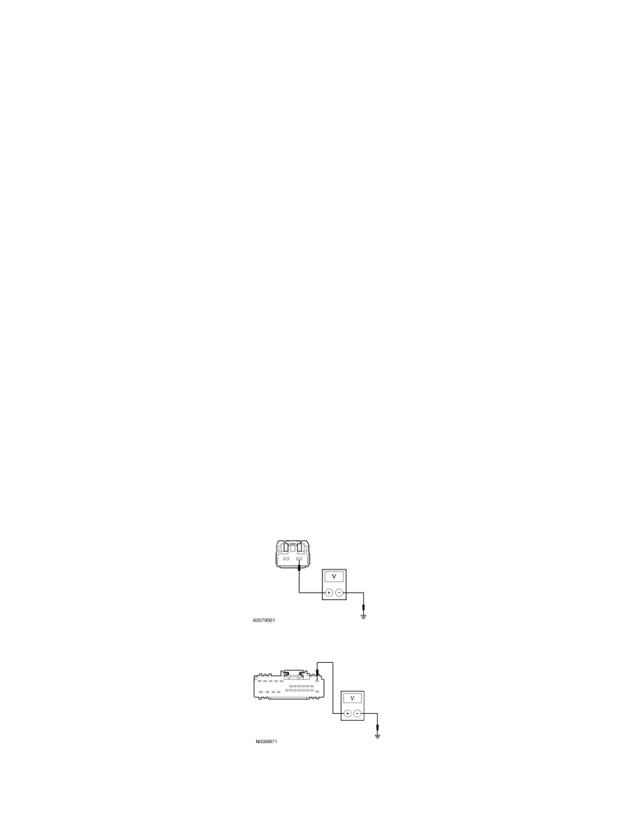
I1 CHECK THE DSM VOLTAGE SUPPLY CIRCUITS FOR AN OPEN
-
Ignition OFF.
-
Disconnect: DSM C341a and DSM C341b.
-
Measure the voltage between the DSM C341a-1, circuit SBB45 (GY/RD), harness side and ground.
-
Measure the voltage between the DSM C341b-1, circuit SBP12 (GN/RD), harness side and ground.
-
Are the voltages greater than 10 volts?
Yes