
F 550 2WD Super Duty V10-6.8L (2009)
-
Is the resistance less than 5 ohms?
Yes
GO to P3.
No
REPAIR the circuit. CONNECT the negative battery cable. CLEAR the DTCs. REPEAT the network test with the scan tool.
-------------------------------------------------
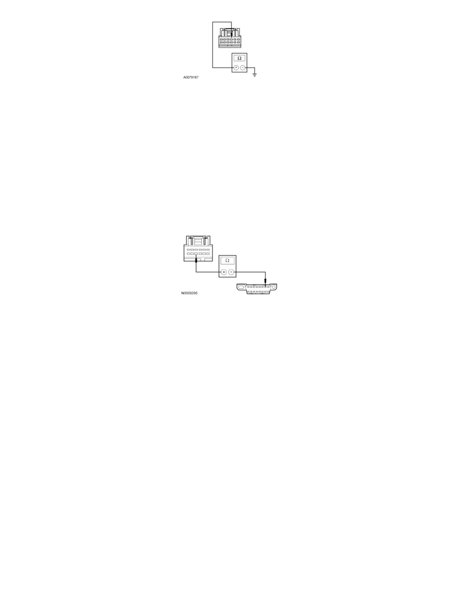
P3 CHECK THE ISO 9141 CIRCUIT FOR AN OPEN BETWEEN THE 4X4 CONTROL MODULE AND THE DLC
-
Disconnect: 4X4 Control Module C281a.
-
Measure the resistance between the 4X4 control module C281a-10, circuit VDB10 (GY), harness side and the Data Link Connector (DLC)
C251-7, circuit VDB10 (GY), harness side.
-
Is the resistance less than 5 ohms?
Yes
CONNECT the negative battery cable. GO to P4.
No
REPAIR the circuit. CONNECT the negative battery cable. REPEAT the network test with the scan tool.
-------------------------------------------------
P4 CHECK FOR CORRECT 4X4 CONTROL MODULE OPERATION
-
Disconnect all the 4X4 control module connectors.
-
Check for:
-
corrosion
-
damaged pins
-
pushed-out pins
-
Connect all the 4X4 control module connectors and make sure they seat correctly.
-
Operate the system and verify the concern is still present.
-
Is the concern still present?
Yes
INSTALL a new 4X4 control module. CLEAR the DTCs. REPEAT the network test with the scan tool.
No
The system is operating correctly at this time. The concern may have been caused by a loose or corroded connector. CLEAR the DTCs. REPEAT the
network test with the scan tool.
-------------------------------------------------