
F 550 2WD Super Duty V10-6.8L (2009)
The Parking Aid Module (PAM) and the 4X4 control module (if equipped) communicate with the scan tool through the ISO 9141 communications
network, circuit VDB10 (GY).
This pinpoint test is intended to diagnose the following:
-
Fuse
-
Wiring, terminals or connectors
-
4X4 control module (if equipped)
-
PAM
PINPOINT TEST R: NO ISO 9141 NETWORK COMMUNICATION
NOTICE: Use the correct probe adapter(s) when making measurements. Failure to use the correct probe adapter(s) may damage the
connector.
NOTE: Most faults are due to connector and/or wiring concerns. Carry out a thorough inspection and verification before proceeding with the Pinpoint
Test. See: Initial Inspection and Diagnostic Overview/Communications Network/Inspection and Verification
NOTE: Failure to disconnect the battery when instructed will result in false resistance readings.
-------------------------------------------------
R1 CHECK THE DLC PINS FOR DAMAGE
-
Ignition OFF.
-
Disconnect the scan tool cable from the DLC.
-
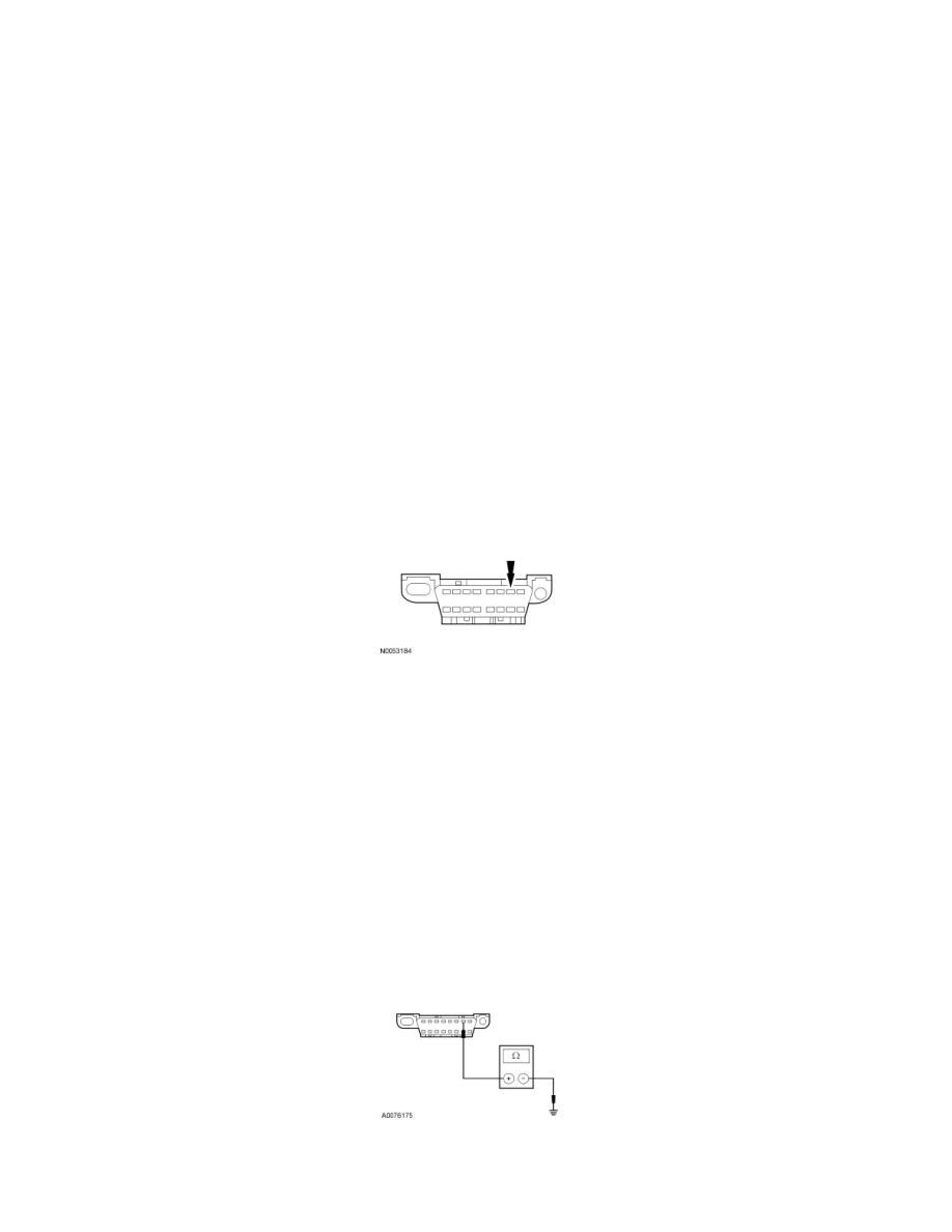
Inspect the Data Link Connector (DLC) pin 7 for damage.
-
Is the DLC pin 7 OK?
Yes
GO to R2.
No
REPAIR the DLC as necessary. CLEAR the DTCs. REPEAT the network test with the scan tool.
-------------------------------------------------
R2 CHECK THE ISO 9141 CIRCUIT FOR A SHORT TO GROUND
-
Disconnect: Negative Battery Cable.
-
Disconnect: 4X4 Control Module C281a (If Equipped).
-
Disconnect: PAM C2023 (If Equipped).
-
Measure the resistance between the DLC C251-7, circuit VDB10 (GY), harness side and ground.
-
Is the resistance greater than 10,000 ohms?
Yes