
F 550 2WD Super Duty V10-6.8L (2009)
REPAIR the circuits. CONNECT all modules. CONNECT the negative battery cable. CLEAR the DTCs. REPEAT the network test with the scan tool.
No
CONNECT all modules. CONNECT the negative battery cable. GO to T39.
-------------------------------------------------
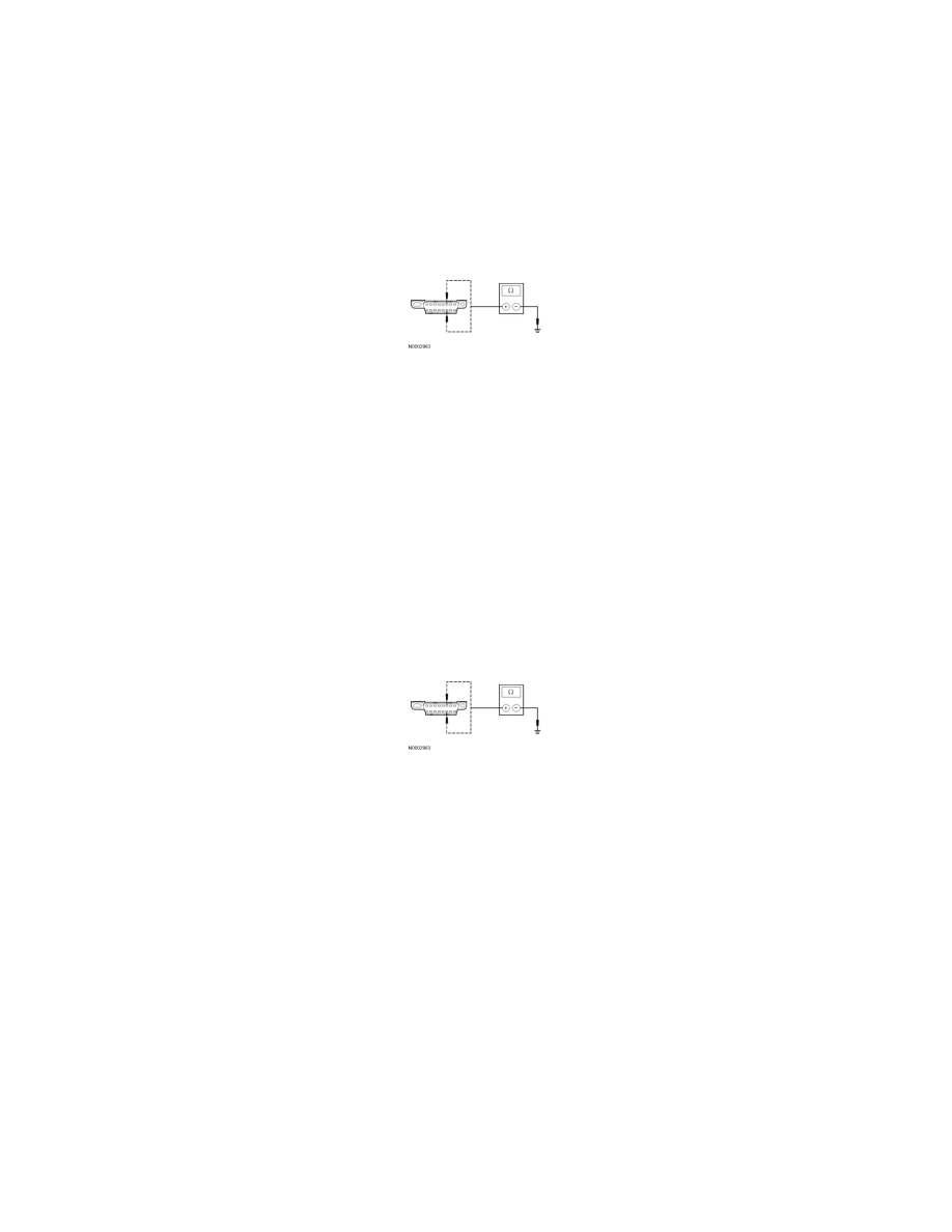
T21 CHECK THE HS-CAN (+) AND HS-CAN (-) CIRCUITS FOR A SHORT TO GROUND WITH THE PCM DISCONNECTED
-
Disconnect: PCM C175b (Gasoline Engine) or C1232b (Diesel Engine).
-
Measure the resistance between the DLC C251-6, circuit VDB04 (WH/BU), harness side and ground; and between the DLC C251-14, circuit
VDB05 (WH), harness side and ground.
-
Are the resistances greater than 5,000 ohms?
Yes
CONNECT the negative battery cable. GO to T31.
No
GO to T22.
-------------------------------------------------
T22 CHECK THE HS-CAN (+) AND HS-CAN (-) CIRCUITS FOR A SHORT TO GROUND WITH THE ABS MODULE DISCONNECTED
-
Disconnect: ABS Module C135.
-
Measure the resistance between the DLC C251-6, circuit VDB04 (WH/BU), harness side and ground; and between the DLC C251-14, circuit
VDB05 (WH), harness side and ground.
-
Are the resistances greater than 5,000 ohms?
Yes
CONNECT all modules. CONNECT the negative battery cable. GO to T32.
No
If the vehicle is equipped with a TBC module, GO to T23.
If the vehicle is not equipped with a TBC module, GO to T24.
-------------------------------------------------
T23 CHECK THE HS-CAN (+) AND HS-CAN (-) CIRCUITS FOR A SHORT TO GROUND WITH THE TBC MODULE DISCONNECTED
-
Disconnect: TBC Module C2142.
-
Measure the resistance between the DLC C251-6, circuit VDB04 (WH/BU), harness side and ground; and between the DLC C251-14, circuit
VDB05 (WH), harness side and ground.