
F 550 2WD Super Duty V10-6.8L (2009)
GO to V19.
No
CONNECT all modules. CONNECT the negative battery cable. GO to V38.
-------------------------------------------------
V19 VERIFY VEHICLE OPTION CONTENT - CDIM
-
Verify the vehicle for a CDIM. This module is present on some diesel engine vehicles.
-
Is the vehicle equipped with a CDIM?
Yes
GO to V20.
No
REPAIR the circuits. CONNECT all modules. CONNECT the negative battery cable. CLEAR the DTCs. REPEAT the network test with the scan tool.
-------------------------------------------------
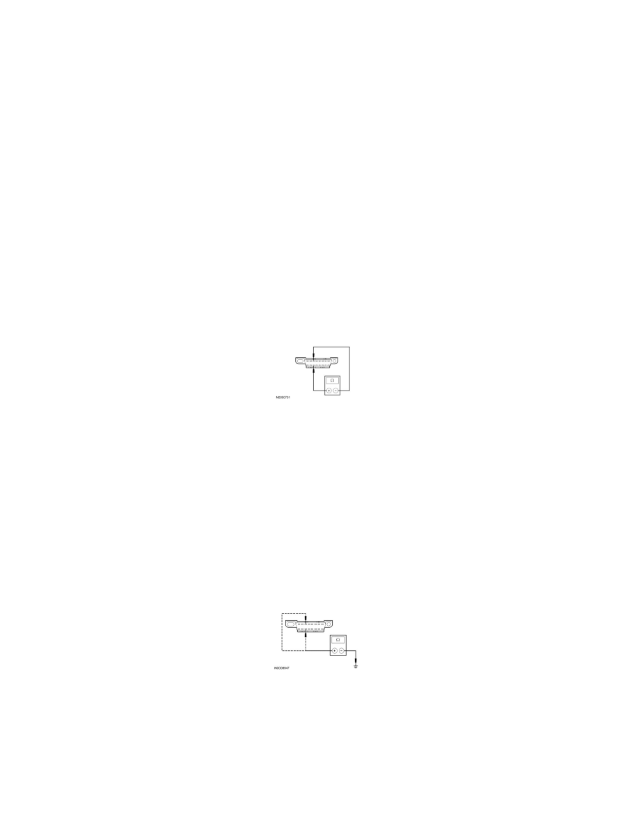
V20 CHECK THE MS-CAN (+) AND MS-CAN (-) CIRCUITS FOR A SHORT TOGETHER WITH THE CDIM DISCONNECTED
-
Disconnect: CDIM C2500.
-
Measure the resistance between the DLC C251-3, circuit VDB06 (GY/OG), harness side and the DLC C251-11, circuit VDB07 (VT/OG), harness
side.
-
Is the resistance less than 5 ohms?
Yes
REPAIR the circuits. CONNECT all modules. CONNECT the negative battery cable. CLEAR the DTCs. REPEAT the network test with the scan tool.
No
CONNECT all modules. CONNECT the negative battery cable. GO to V39.
-------------------------------------------------
V21 CHECK THE MS-CAN (+) AND MS-CAN (-) CIRCUITS FOR A SHORT TO GROUND WITH THE SJB DISCONNECTED
-
Disconnect: SJB C2280b.
-
Measure the resistance between the DLC C251-3, circuit VDB06 (GY/OG), harness side and ground; and between the DLC C251-11, circuit
VDB07 (VT/OG), harness side and ground.
-
Are the resistances greater than 5,000 ohms?
Yes
CONNECT the negative battery cable. GO to V31.
No
If the vehicle is equipped with a SDARS module, GO to V22.