
F 550 4WD Super Duty V10-6.8L (2009)
Trailer Brake Control Module: Pinpoint Tests
Pinpoint Test A: DTC B1863
Auxiliary Brake System - Trailer Brake Control (TBC) Module
Pinpoint Tests
Pinpoint Test A: DTC B1863
NOTE: Carry out all pinpoint tests without a trailer connected to the vehicle.
Refer to Wiring Diagram Set 95, Trailer/Camper Adapter for schematic and connector information. See: Diagrams/Electrical Diagrams/Diagrams By
Number
Normal Operation
The Trailer Brake Control (TBC) module receives fused battery voltage from Battery Junction Box (BJB) fuse 5 (30A) along circuit SBB05 (GY/RD)
and fused ignition voltage from Smart Junction Box (SJB) fuse 33 (10A) along circuit CBP33 (WH/BN). The ground path for the TBC module is
provided along circuit GD115 (BK/GY).
-
B1863 TBC Ground Open Circuit - If an open occurs in the wiring, a connector condition causes an open in the ground circuit or if an internal
failure of the TBC module causes an open in the ground circuit, the TBC module will set DTC B1863. The TBC module will also disable trailer
braking and send a TRAILER BRAKE MODULE FAULT message to the message center. A trailer must be connected for this DTC to set.
This pinpoint test is intended to diagnose the following:
-
Wiring, terminals or connectors
-
TBC module
PINPOINT TEST A: DTC B1863
NOTICE: Use the Flex Probe Kit for all test connections to prevent damage to the wiring terminals. Do not use standard multi-meter probes.
-------------------------------------------------
A1 CHECK THE TBC MODULE GROUND CIRCUIT FOR AN OPEN
-
Ignition OFF.
-
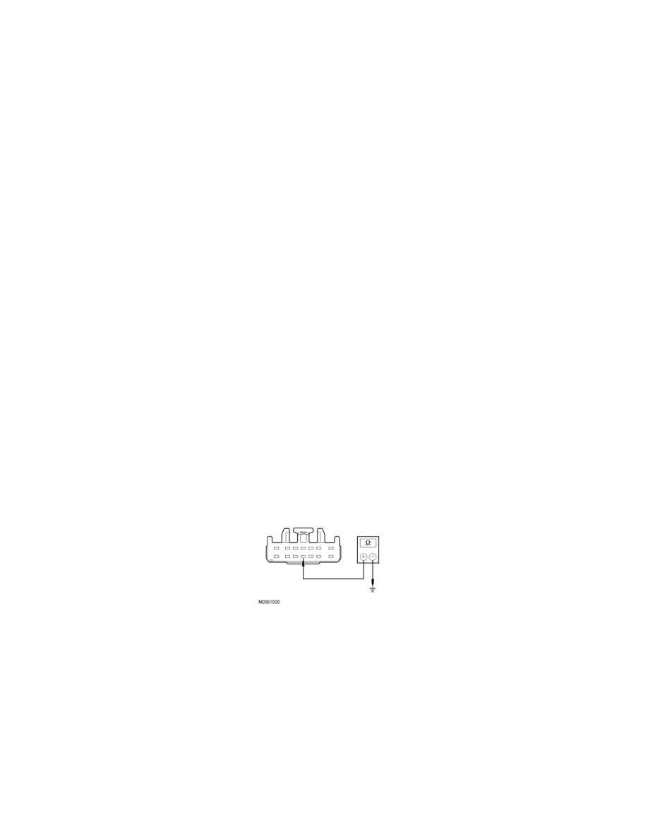
Disconnect: TBC module C2124.
-
Measure the resistance between TBC module C2124-11, circuit GD115 (BK/GY), harness side and ground.
-
Is the resistance less than 5 ohms?
Yes
GO to A2.
No
REPAIR circuit GD115 (BK/GY). CLEAR the DTCs. REPEAT the self-test.
-------------------------------------------------
A2 CHECK FOR CORRECT TBC MODULE OPERATION
-
Check the TBC module connector for:
-
corrosion.
-
pushed-out pins.