
F 550 4WD Super Duty V10-6.8L (2009)
REPAIR the circuit for high resistance. CLEAR the DTC. REPEAT the self-test.
-------------------------------------------------
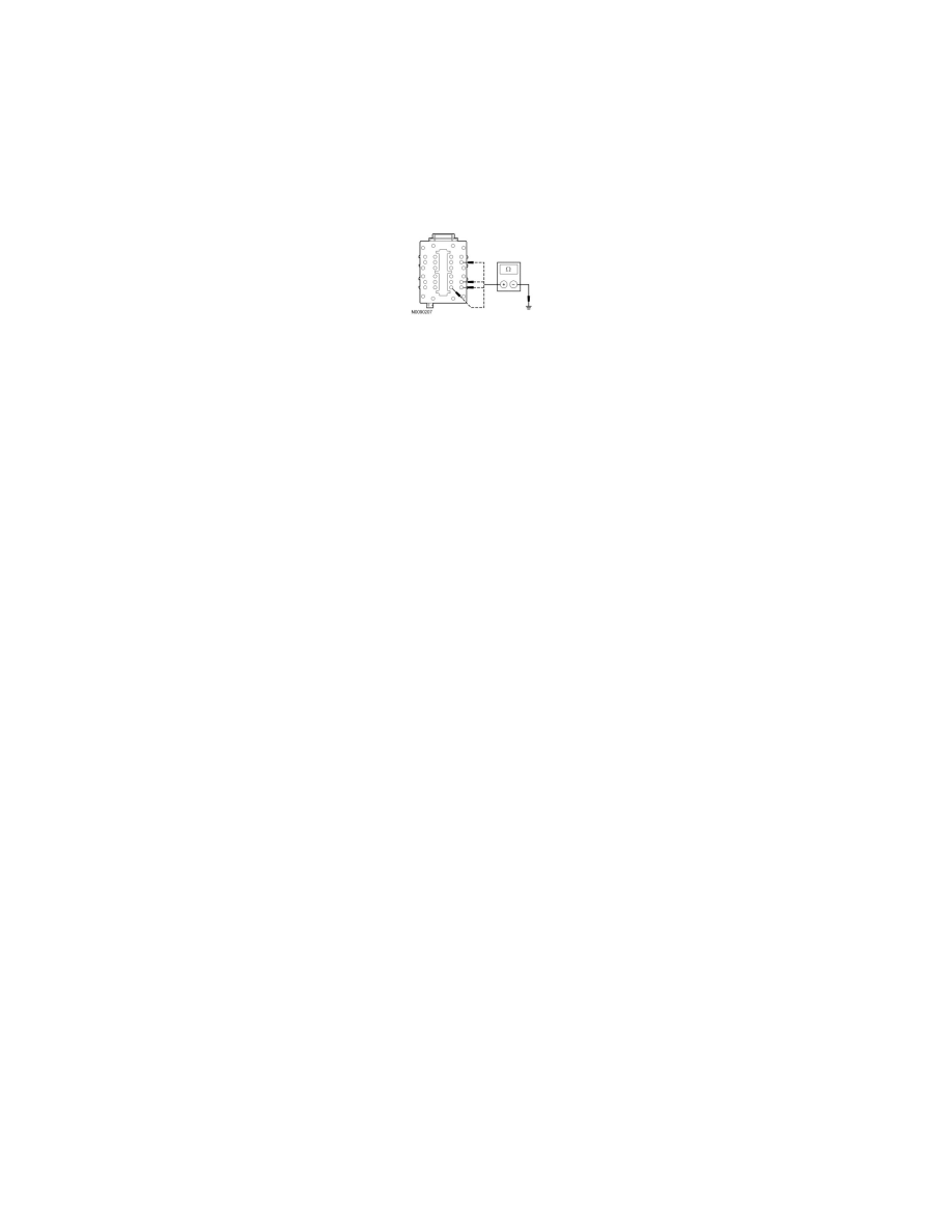
D5 CHECK THE SJB GROUND CIRCUIT
-
Ignition OFF.
-
Disconnect: Negative Battery Cable.
-
Disconnect: SJB C2280D.
-
Measure the resistance between the SJB C2280D-7, 8, 12, 24, circuit GD179 (BK/VT), harness side and ground.
-
Is the resistance less than 5 ohms?
Yes
CONNECT the negative battery cable. GO to D6.
No
REPAIR the circuit for high resistance. CONNECT the negative battery cable. TEST the system for normal operation.
-------------------------------------------------
D6 CHECK FOR CORRECT SJB OPERATION
-
Disconnect the SJB connectors.
-
Check for:
-
corrosion
-
damaged pins
-
pushed-out pins
-
Connect the SJB connectors and make sure they seat correctly.
-
Operate the system and verify the concern is still present.
-
Is the concern still present?
Yes
INSTALL a new SJB. REFER to Smart Junction Box (SJB) See: Power and Ground Distribution/Power Distribution Module/Service and Repair/Smart
Junction Box (SJB). TEST the system for normal operation.
No
The system is operating correctly at this time. The concern may have been caused by a loose or corroded connector.
-------------------------------------------------
Pinpoint Test E: DTC U0155
Smart Junction Box (SJB)
Pinpoint Tests
Pinpoint Test E: DTC U0155
Normal Operation
-
DTC U0155 (Lost Communication With Instrument Panel Cluster (IC) Control Module) - set by the SJB whenever it receives invalid data from
the Instrument Cluster (IC).
This pinpoint test is intended to diagnose the following:
-
Module communication