
F 550 4WD Super Duty V10-6.8L (2009)
GO to R3.
No
REPAIR the circuit. CONNECT the negative battery cable. CLEAR the DTCs. REPEAT the network test with the scan tool.
-------------------------------------------------
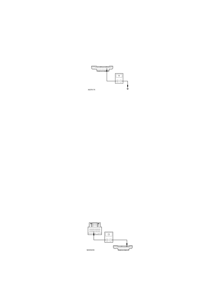
R3 CHECK THE ISO 9141 CIRCUIT FOR A SHORT TO VOLTAGE
-
Ignition ON.
-
Measure the voltage between the DLC C251-7, circuit VDB10 (GY), harness side and ground.
-
Is any voltage present?
Yes
REPAIR the circuit. CONNECT the negative battery cable. CLEAR the DTCs. REPEAT the network test with the scan tool.
No
GO to R4.
-------------------------------------------------
R4 VERIFY VEHICLE OPTION CONTENT - 4X4 CONTROL MODULE
-
Verify vehicle option content.
-
Is the vehicle equipped with a 4X4 control module?
Yes
GO to R5.
No
GO to R7.
-------------------------------------------------
R5 CHECK VDB10 (GY) FOR AN OPEN BETWEEN THE 4X4 CONTROL MODULE AND THE DLC
-
Ignition OFF.
-
Measure the resistance between the 4X4 control module C281a-10, circuit VDB10 (GY), harness side and the DLC C251-7, circuit VDB10 (GY),
harness side.
-
Is the resistance less than 5 ohms?
Yes
GO to R6.