
F 550 4WD Super Duty V10-6.8L (2009)
Multiple piece driveshafts
4. NOTE: Repeat this step for each center support bearing on the driveshaft.
NOTE: It is not necessary to remove the U-joint snap ring, if equipped, for these measurements.
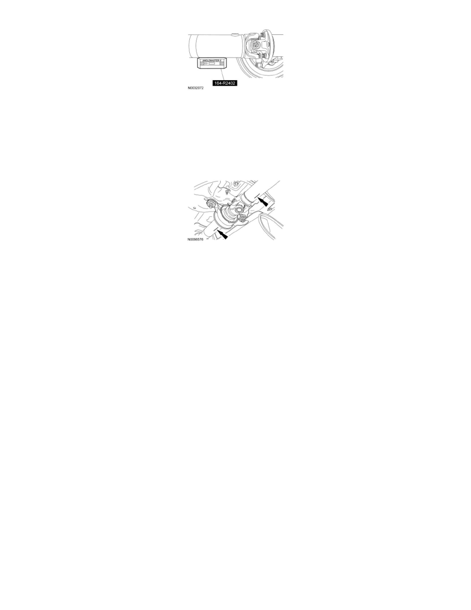
Using the Anglemaster II Driveline Inclinometer/Protractor, measure the slope of the components in front and behind the center support bearing
U-joint in the area indicated. Record the front component as angle A and the rear component as angle B.
All vehicles
5. NOTE: When 2 connected components slope in the same direction, subtract the smallest number from the larger number to find the U-joint
operating angle. When 2 connected components slope in the opposite direction, add the measurements to find the U-joint operating angle.
Calculate the difference in the slope of the components to determine the U-joint operating angle.
-
The U-joint operating angle is the angle formed by 2 yokes connected by a cross and bearing kit. Ideally, the operating angles on each
connection of the driveshaft must:
-
be equal or within one degree of each other.
-
have a 3 degree maximum operating angle.
-
have at least one-half of one degree continuous operating angle.
6. If the angle is not within specifications, repair or adjust to obtain the correct angle. Inspect the engine mounts, transmission mounts, center support
bearing mounting, rear suspension, rear axle, rear axle mounting or the frame for wear or damage.
Driveline Angle Adjustment
Driveline Angle Adjustment
NOTE: Some vehicles may exhibit a drive-away shudder or vibration under moderate to heavy acceleration from a stop, especially when heavily loaded
or when towing a trailer. It is important to confirm how the vehicle is driven the majority of the time (loaded or unloaded), as adjusting the driveline
angle may result in a shudder or vibration with the vehicle unloaded. This procedure should only be used to correct or improve a shudder or vibration
that occurs only when the vehicle is loaded.
All Vehicles
NOTE: The driveline angle must be measured with the vehicle loaded to determine the amount of adjustment necessary to correct the condition.
1. Measure the driveline angle. Refer to Driveline Angle Measurement. See: Driveline Angle Measurement
-
If the driveline does not have an optimum 3 degree operating range, proceed to the following adjustment steps using the parts listed in the table
below.