
F 550 4WD Super Duty V10-6.8L (2009)
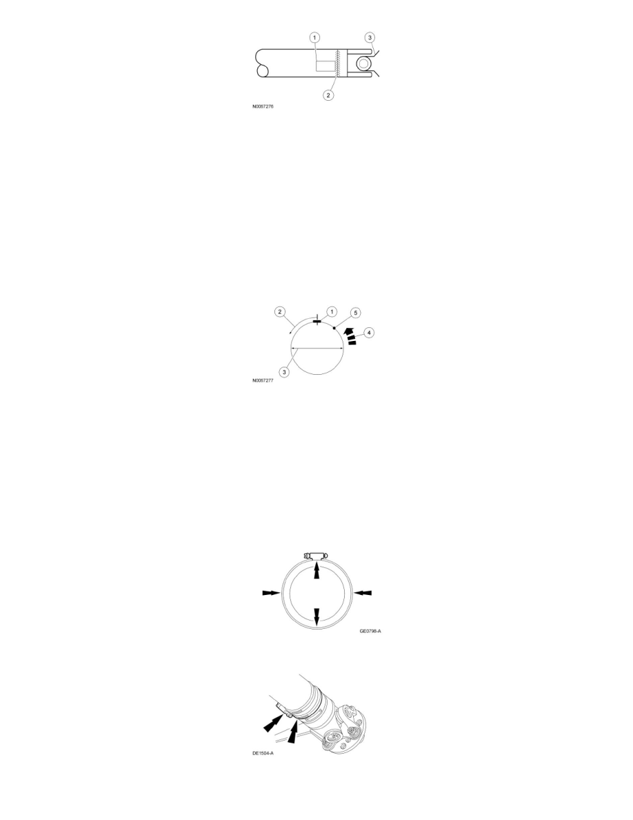
9. Remove the test weight, then install the recommended weight at the position directed by the Mastertech(R) Series MTS 4000 Driveline Balance
and NVH Analyzer (Vetronix). Using a metal band and epoxy, secure the test weight to the driveshaft, as shown in the figure below.
1. Test weight.
2. Measure in this direction.
3. Driveshaft diameter.
4. Directional rotation.
5. Balance weight relative to test weight centerline.
-
The results are displayed with respect to the location to where the test weight was placed.
All vehicles
10. Using the Mastertech(R) Series MTS 4000 Driveline Balance and NVH Analyzer (Vetronix), run a third test to verify the repair.
Driveshaft Balancing - Hose Clamp Method
1. Install 1 or 2 hose clamps on the driveshaft, near the rear. Position of the hose clamp head(s) can be determined through trial and error.
2. Mark the rear of the driveshaft into 4 approximately equal sectors and number the marks 1 through 4. Install a hose clamp on the driveshaft with its
head at position No. 1, as shown in the figure below. Check for vibration at road speed. Recheck with the clamp at each of the other positions to
find the position that shows minimum vibration. If 2 adjacent positions show equal improvement, position the clamp head between them.
3. If the vibration persists, add a second clamp at the same position and recheck for vibration.
4. If no improvement is noted, rotate the clamps in opposite directions, equal distances from the best position determined in Step 2. Separate the
clamp heads about 13 mm (1/2 in) and recheck for vibration at the road speed.