
F 550 4WD Super Duty V10-6.8L VIN S (2000)
General Module: Service and Repair
REMOVAL
NOTE: The GEM must be reconfigured upon replacement. Refer to the scan tool help screen on the Ford Service Function (FSF) card to program tire
size and axle ratio.
1. Disconnect the battery ground cable. For additional information, refer to Battery.
CAUTION: Electronic modules are sensitive to electrical charges. If exposed to these charges, damage may result.
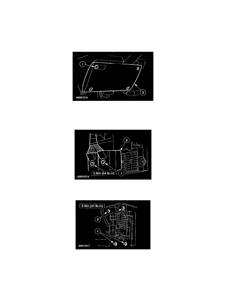
2. Remove the instrument panel steering column cover.
1
Unlock the retainers.
2
Remove the instrument panel steering column cover.
CAUTION: Use care when removing the instrument panel steering column cover or damage to the cover locating tab may occur.
3. Disconnect the bulkhead connectors from the instrument panel fuse junction panel.
1
Loosen the bolts.
2
Disconnect the bulkhead connectors.
4. Position the instrument panel fuse junction panel aside.
1
Remove the nuts.
2
Remove the bolts.