
F 550 4WD Super Duty V10-6.8L VIN S (2000)
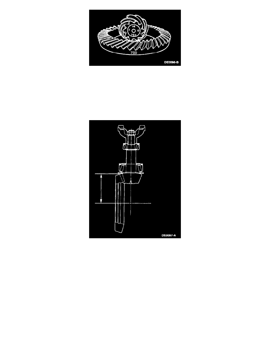
12. NOTE: The differential ring gear and pinion is only available in a matched set. Matching numbers etched on both the differential ring gear and
pinion are for verification. If installing a new differential ring gear and pinion, verify these numbers match before proceeding with assembly. The
end of the pinion with the etched figures is the "button" end.
NOTE: Use the gear contact pattern method to verify the final pinion position is valid.
Shim the pinion as follows:
^
Etched on the button end of each pinion is a zero (0), or a plus (+) or minus (-) with a number. This number indicates the best running position
for each particular differential ring gear. Shimming behind the inner pinion bearing controls this dimension.
13. Measure between the centerline of the differential ring gear to the back face of the drive pinion.
^
For model 50 axles, the distance between the centerline of the differential ring gear to the back face of the drive pinion is 117.6 mm (4.630
inch).
^
For model 60 axles, the distance between the centerline of the differential ring gear to the back face of the drive pinion is 127 mm (5.0 inch).
14. If reusing the old differential ring gear and pinion, proceed as follows:
^
Measure and record the old drive pinion position shim thickness and select a new shim of the same dimension.
^
To change the pinion adjustment, drive pinion position shims are available in the thickness shown in the following charts. Measure each shim
separately with a micrometer.