
F 550 4WD Super Duty V8-7.3L DSL Turbo VIN F (2001)
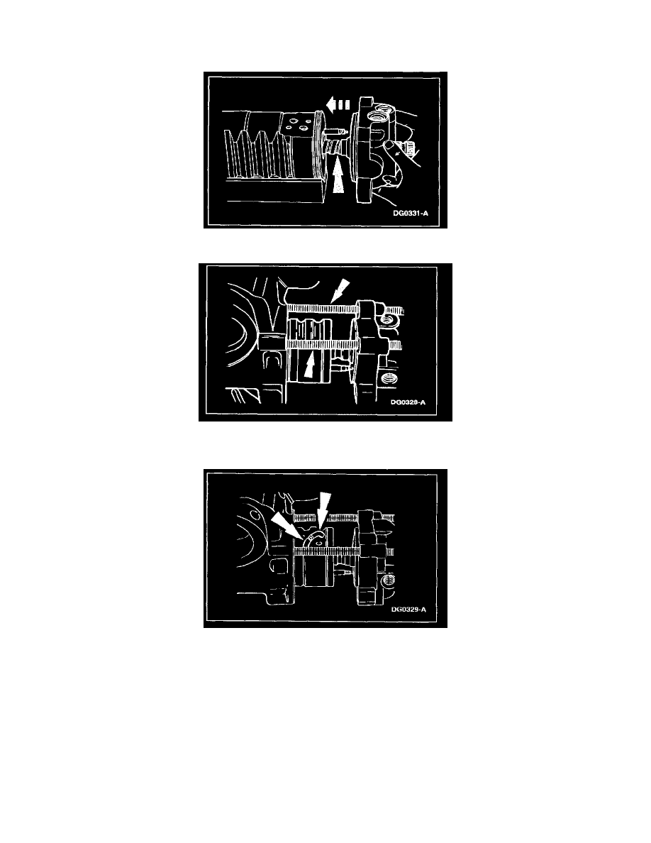
9. Place the rack piston in the housing piston bore with ball return guide holes up.
-
Apply clean oil to the housing cylinder bore.
10. Insert the worm shaft into the rack piston close to maximum depth, without the valve housing making contact with the poppet stem.
11. Insert two 7/16-14 Ready Bolts through the valve housing bolt holes and tighten into housing to support the worm shaft.
-
Line up the rack piston ball guide holes with the worm ball track grooves by rotating the input shaft.
12. WARNING: Do not seat guides with a hammer. Damage to guides can result in subsequent lockup or loss of steering.
CAUTION: If a new rack piston or a new input shaft, valve, worm subassembly is being assembled, the balls removed from the unit must be
discarded and a service ball kit utilized. The balls in a service ball kit are sized to function in the ball track guide path as altered by component
replacement.
CAUTION: When using the service ball kit, the correct quantity of service balls: TAS4O-32.
NOTE: Compare the new guides with the guides removed from the gear: use the ones that look the same. Left guides are copper-plated, right
guides are unplated.
Assemble the new ball return guide halves into the rack piston until seated and rotate the input shaft slightly if necessary.