
F 550 4WD Super Duty V8-7.3L DSL Turbo VIN F (2001)
8. Apply oil and assemble the other thrust bearing and then the thin thrust washer over the ball groove end of the worm and seat them against the
shoulder of the input shaft, valve and worm assembly.
9. NOTE: Be sure the valve housing, adjuster locknut and bearing adjuster threads are clean and free of any staking burrs that would impede the
locknut from turning freely on the adjuster or the adjuster turning freely in the valve housing.
Lightly oil a new O-ring and assemble it into the seal groove in the bearing adjuster. Oil and work a new seal ring into the same groove and
smooth it out.
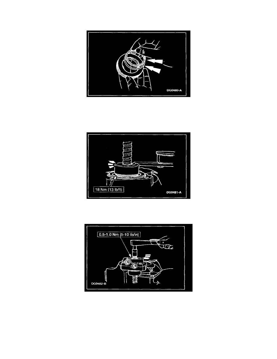
10. Lightly oil and assemble the bearing adjuster over the worm and into the valve housing.
-
Tighten the adjuster to specification, using a torque wrench inserted in Adjuster Tool. This will seat the components.
-
Back off adjuster one-quarter to one-half turn.
11. With an inch-pound torque wrench on the input shaft, note the torque required to rotate the input shaft 360 degrees in each direction. Tighten the
bearing adjuster to increase the maximum torque (as specified) at the input shaft over the specification previously noted in Step 10.