
Festiva L4-81 1.3L SOHC (1988)
Alternator: Testing and Inspection
Alternator Overcharges
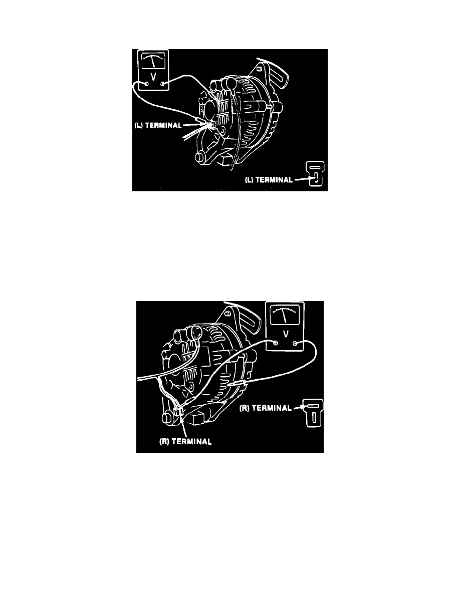
Fig. 1 Voltage output test connections
Voltage Output Test
The following test must be performed with a fully charged battery.
1.
Connect test leads of charging system analyzer tool 078-00005 or equivalent to vehicle, following tool manufacturer's instructions, then start
engine and run at approximately 2500 RPM.
2.
With all electrical accessories off, read and record current output.
3.
If reading is less than 5 amps, connect positive lead of voltmeter to ``L'' terminal of alternator connector and negative lead to alternator case,
Fig.
1. Ensure that ``L'' terminal connector remains connected during test.
4.
Restart engine, run at 2500 RPM, and read and record voltage output. If reading is 14.4-15 volts, alternator is operating properly. If reading is
greater than 15 volts, proceed to ``Regulator Power Source Test.''
Fig. 2 Regulator power source test connections
Regulator Power Source Test
1.
Turn ignition switch On, but do not start engine.
2.
Disconnect ``R'' terminal connector from rear of alternator, then connect voltmeter positive lead to ``R'' terminal connector harness and negative
lead to alternator case,
Fig. 2. Read and record voltage.
3.
If reading obtained is at base voltage recorded earlier, proceed to ``Rotor Field Coil Test.'' If reading is less than base voltage, check for defective
circuit between ignition switch and ``R'' terminal.
4.
Reconnect terminal connector.