
Festiva L4-81 1.3L SOHC (1988)
Axle Shaft: Service and Repair
Disassembly/Assembly
NOTE: The halfshafts on these vehicles use two different types of CV joints. The inboard joints are repairable Rzeppa type joints, while the outboard
joints are non-repairable Birfield joints.
DISASSEMBLY
1.
Clamp shaft assembly in soft jaw vise.
2.
Using suitable screwdriver, pry up locking clips of boot bands, then cut bands off boots and discard.
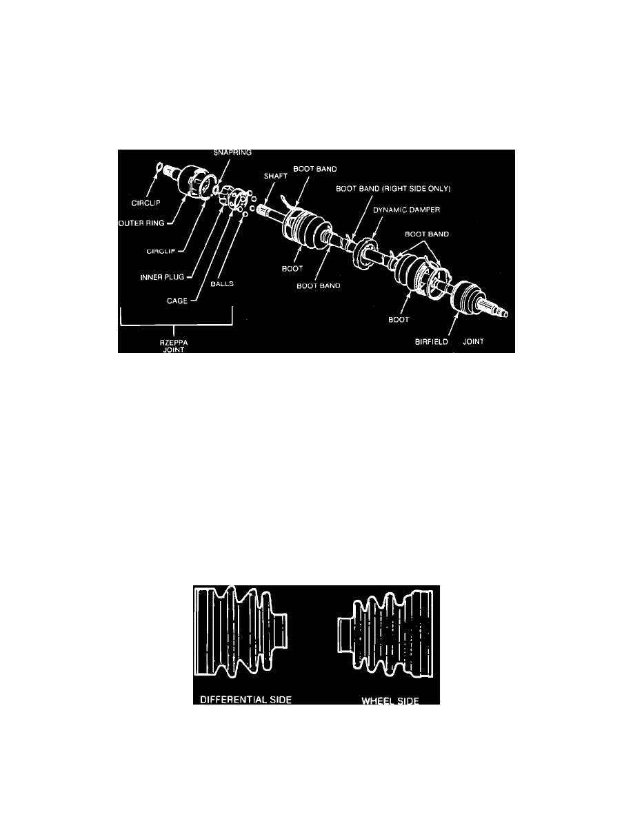
Fig. 2 Disassembled View Of Halfshaft. Rzeppa Type
3.
Slide boot off Rzeppa joint, Fig. 2, then paint alignment marks on outer ring and shaft to aid assembly.
4.
Remove large circlip retaining Rzeppa joint to outer ring. If no damage is evident, leave circlip installed.
5.
Withdraw outer ring from Rzeppa joint.
6.
Place punch marks on shaft and joint inner plug, then remove snap ring retaining shaft to plug and withdraw Rzeppa joint assembly from shaft.
7.
Paint alignment marks on inner plug and cage to aid assembly, then position blade of screwdriver between inner plug and cage and remove balls.
8.
Turn cage approximately 30°, then separate cage from inner plug.
9.
Remove Rzeppa joint inner boot and dynamic damper (right shaft only) from shaft.
10.
Remove Birfield joint inner boot from shaft. Do not remove Birfield joint from shaft unless damage or excessive wear is evident. If
necessary, replace complete Birfield joint assembly as required.
INSPECTION
1.
Clean all metal parts in suitable solvent and dry with compressed air.
2.
Check shaft for twisting and/or worn or scored splines, joint components for rust, damage or excessive wear, and boots for cracks, damage or
deterioration.
3.
Replace all components as necessary.
Fig. 3 Boot identification
ASSEMBLY
1.
Install new Birfield joint, if necessary.
2.
Place tape on shaft splines, then install wheel side boot. Wheel side and differential side boots are not interchangeable. Refer to Fig. 3 for