ford Workshop Repair Guides

Ford Workshop Service and Repair Manuals

General Procedures > < Ignition Switch
Engine System - General Information - Engine Fiesta 1996 (08/1995-02/2002)
Diagnosis and Testing

Since troubleshooting actually begins when repairs are taken on, the following procedure is recommended:

  1. Check customer concern is clear. If necessary, reconstruct the concern on the vehicle.
  1. If the concern cannot be reproduced, carry out a road test and/or a visual check with the aid of the following table:

Visual Inspection Chart

Mechanical
  • Leaks in the cooling system
  • Leaks in the engine oil circuit
  • Leaks in the fuel system
  • Visibly damaged or worn parts
  • Loose or missing nuts or bolts
  1. If a concern can be clearly identified by visual inspection, resolve it and check that the system operates as it should.
  1. If the fault cannot be clearly identified, use the symptom chart below to identify the fault.

Symptom Chart

Symptom Possible Sources Action
Loss of oil
*
Use of the wrong type of engine oil.
*
Establish what oil was last used in the engine (refer to the last bill or oil label), compare it with the specification and change it if necessary.
*
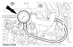
Pressure in the cylinder block too high
-
Faulty crankcase ventilation system
-
Poor sealing between combustion chamber and crankcase
*
Unscrew/remove the cylinder head cover cap. Close off the opening by hand. If pressure can be felt when the engine is running:
-
Check that the crankcase ventilation system works correctly, repair it if necessary.
-
Screw the compressed air lines into the spark plug hole of each cylinder in turn, apply compressed air and check for escaping air when the cylinder head cover cap is unscrewed. If there is a perceptible flow of air, inspect the cylinder liner surfaces and pistons for damage and measure.
REFER to General Procedures in this section.
*
Leaking as a result of damaged oil seal or incorrect oil seal carrier alignment.
-
Camshaft
-
Crankshaft, front or rear.
*
Check the alignment of the seal carrier and correct as necessary. Renew the oil seal.
*
Damaged gaskets or mating faces
-
Cylinder head gasket or mating face is damaged, engine oil can escape from the engine between cylinder head and cylinder block or get into the cooling system.
*
Check gaskets and mating faces for damage.
-
Open the coolant expansion tank cap and check for oil sludge or a film of oil on the surface of the coolant.
-
Remove the cylinder head. Engine - 1.3L REFER to Section  303-01A Engine / 303-01B Engine / 303-01C Engine / 303-01D Engine / 303-01E Engine.Engine - 1.25L, 1.4L and 1.6L - REFER to Section  303-01A Engine / 303-01B Engine / 303-01C Engine / 303-01D Engine / 303-01E Engine.Engine - 1.8L Diesel-Endura DE - REFER to Section  303-01A Engine / 303-01B Engine / 303-01C Engine / 303-01D Engine / 303-01E Engine.Engine - 1.8L Diesel-Endura DI - REFER to Section  303-01A Engine / 303-01B Engine / 303-01C Engine / 303-01D Engine / 303-01E Engine.Check the mating faces and cylinder head gasket, and check that the cylinder head mating face is level.
REFER to General Procedures in this section.
If necessary, re-work or renew the cylinder head.
*
Leaks from oil carrying or coated engine parts and attached components.
*
Locate cracks in oil-carrying components or the basic engine by means of a UV leak test, and renew the relevant components or seals.
*
Faulty crankcase ventilation system
-
Hoses or ventilation/breather valve are blocked. This causes excessive pressure in the crankcase which causes more oil to enter the combustion chamber.
-
The crankcase ventilation system oil thrower is faulty and engine oil can reach the combustion chamber via the inlet manifold.
*
Check that the crankcase ventilation system works correctly, repair it if necessary.
*
Damaged cylinder liners or too much clearance on engine components.
-
Pistons
-
Piston rings (clearance in groove and end gap)
-
Cylinder liners
-
Valve stems and guides.
*
Check the running surfaces and clearances of the individual engine components, and renew if necessary. Renew the cylinder block if necessary.
-
Pistons
-
Piston rings
-
Cylinder liners
-
Valve stems and guides
*
Damaged gaskets or mating faces
-
Cylinder head gasket or mating face is damaged, and engine oil can enter the combustion chamber.
-
Valve stem oil seals are damaged and engine oil can enter the combustion chamber between valve stem and valve guide. This becomes particularly apparent on overrun.
*
Check gaskets and mating faces for damage.
-
Remove the cylinder head. Engine - 1.3L REFER to Section  303-01A Engine / 303-01B Engine / 303-01C Engine / 303-01D Engine / 303-01E Engine.Engine - 1.25L, 1.4L and 1.6L - REFER to Section  303-01A Engine / 303-01B Engine / 303-01C Engine / 303-01D Engine / 303-01E Engine.Engine - 1.8L Diesel-Endura DE - REFER to Section  303-01A Engine / 303-01B Engine / 303-01C Engine / 303-01D Engine / 303-01E Engine.Engine - 1.8L Diesel-Endura DI - REFER to Section  303-01A Engine / 303-01B Engine / 303-01C Engine / 303-01D Engine / 303-01E Engine.Check the mating faces and cylinder head gasket, and check that the cylinder head mating face is level.
REFER to General Procedures in this section.
If necessary, re-work or renew the cylinder head.
-
Renew the valve stem oil seals. Engine - 1.3L REFER to Section  303-01A Engine / 303-01B Engine / 303-01C Engine / 303-01D Engine / 303-01E Engine.Engine - 1.25L, 1.4L and 1.6L - REFER to Section  303-01A Engine / 303-01B Engine / 303-01C Engine / 303-01D Engine / 303-01E Engine.Engine - 1.8L Diesel-Endura DE - REFER to Section  303-01A Engine / 303-01B Engine / 303-01C Engine / 303-01D Engine / 303-01E Engine.Engine - 1.8L Diesel-Endura DI - REFER to Section  303-01A Engine / 303-01B Engine / 303-01C Engine / 303-01D Engine / 303-01E Engine.
Coolant consumption
*
Damaged gaskets or mating faces
-
The cylinder head gasket or mating face is damaged. Coolant can enter the combustion chamber or the crankcase.
*
Check the gaskets and mating faces for damage.
-
Remove the cylinder head. Engine - 1.3L REFER to Section  303-01A Engine / 303-01B Engine / 303-01C Engine / 303-01D Engine / 303-01E Engine.Engine - 1.25L, 1.4L and 1.6L - REFER to Section  303-01A Engine / 303-01B Engine / 303-01C Engine / 303-01D Engine / 303-01E Engine.Engine - 1.8L Diesel-Endura DE - REFER to Section  303-01A Engine / 303-01B Engine / 303-01C Engine / 303-01D Engine / 303-01E Engine.Engine - 1.8L Diesel-Endura DI - REFER to Section  303-01A Engine / 303-01B Engine / 303-01C Engine / 303-01D Engine / 303-01E Engine.Check the mating faces and cylinder head gasket, and check that the cylinder head mating face is flat.
REFER to General Procedures in this section.
If necessary, re-work or renew the cylinder head.
*
Cracks or material breaks in engine components around which coolant flows, such as cylinder liner surfaces and the cylinder head.
*
Identify the damaged engine component and renew it.
Engine will not start
*
Battery or wiring is faulty.
*
Check the battery, electrical connections and cables. REFER to Section  414-00 Charging System - General Information.
*
Starter motor or wiring is faulty
*
Check the starter system REFER to Section  303-06 Starting System.
*
Fault in fuel system.
-
Fuel tank is empty.
*
-
Check level of fuel in tank.
*
Fault in ignition system (petrol engines only).
*
Check the ignition system Endura-E and Zetec-SE - REFER to Section  303-07 Engine Ignition.
*
Fault in engine management system.
*
*
Intake system is faulty
-
Air leak in intake system.
-
Blocked intake air filter.
-
Faulty idle air control valve.
*
Check the intake system REFER to Section  303-12 Intake Air Distribution and Filtering.
*
Fault in valve train.
-
Burned out exhaust valve
-
Timing incorrectly adjusted
-
Toothed belt ripped or damaged.
*
Connect compressed air to the cylinders. If air flows out through the intake manifold or the exhaust pipe, check the valve train.
*
Engine components faulty
-
Burned out piston
-
Piston rings
-
Cylinder Head Gasket
-
Big-end and/or main bearing journals
*
Connect compressed air to the cylinders. If air is escaping from the opened cylinder head cover cap, detach the cylinder head in accordance with the operation and check the components. Engine - 1.3L REFER to Section  303-01A Engine / 303-01B Engine / 303-01C Engine / 303-01D Engine / 303-01E Engine.Engine - 1.25L, 1.4L and 1.6L - REFER to Section  303-01A Engine / 303-01B Engine / 303-01C Engine / 303-01D Engine / 303-01E Engine.Engine - 1.8L Endura-Diesel DE- REFER to Section  303-01A Engine / 303-01B Engine / 303-01C Engine / 303-01D Engine / 303-01E Engine.Engine - 1.8L Endura-Diesel DI - REFER to Section  303-01A Engine / 303-01B Engine / 303-01C Engine / 303-01D Engine / 303-01E Engine.
Poor power development / fuel consumption too high / engine runs roughly
*
Fault in fuel system.
*
*
Fault in ignition system (petrol engines only).
*
Check the ignition system Endura-E and Zetec-SE - REFER to Section  303-07 Engine Ignition.
*
Fault in engine management system.
*
*
Intake system is faulty
-
Air leak in intake system.
-
Air cleaner is blocked
-
Idle air control valve faulty.
*
Check the intake system REFER to Section  303-12 Intake Air Distribution and Filtering.
*
Fault in valve train.
-
Burned out exhaust valve
-
Timing incorrectly adjusted
-
Toothed belt ripped or damaged.
*
Connect compressed air to the cylinders. If air escapes from the intake manifold or the exhaust pipe, check the valve train.
*
Faulty engine components
-
Piston burned out
-
Piston rings
-
Cylinder Head Gasket
-
Big-end and/or main bearing journal
*
Connect compressed air to the cylinders. If air is escaping from the opened cylinder head cover cap, detach the cylinder head and check the components. Dismantle the engine if necessary and check the components. Engine - 1.3L REFER to Section  303-01A Engine / 303-01B Engine / 303-01C Engine / 303-01D Engine / 303-01E Engine.Engine - 1.25L, 1.4L and 1.6L - REFER to Section  303-01A Engine / 303-01B Engine / 303-01C Engine / 303-01D Engine / 303-01E Engine.Engine - 1.8L Diesel-Endura DE - REFER to Section  303-01A Engine / 303-01B Engine / 303-01C Engine / 303-01D Engine / 303-01E Engine.Engine - 1.8L Diesel-Endura DI - REFER to Section  303-01A Engine / 303-01B Engine / 303-01C Engine / 303-01D Engine / 303-01E Engine.
Noise development
*
Misfiring/backfiring
-
Fuel has wrong octane number (petrol engines only), or the wrong type of fuel is in the fuel tank.
-
Fault in ignition system (petrol engines only).
-
Engine temperature too high
-
Carbon deposits in the combustion chamber start to glow and cause misfiring
-
Timing incorrectly adjusted, which causes misfiring in the intake/exhaust system.
*
Determine the cause of the misfiring and rectify it.
-
Determine which type of fuel was last put in the tank (note the country specific fuel specifications).
-
Check the ignition system Endura-E and Zetec-SE - REFER to Section  303-07 Engine Ignition.
-
Check the engine cooling REFER to Section  303-03 Engine Cooling.
-
Remove the carbon deposits by using fuel additives and driving more carefully
-
Check the valve timing.
*
Fault in valve train.
-
Valve clearance too large, resulting from faulty bucket or hydraulic tappet or incorrectly adjusted valve clearance.
-
Valve timing incorrectly adjusted - valves and pistons are touching.
-
Timing belt or timing chain split or damaged.
*
Check the valve train
-
Set the valve clearance (if possible) or renew the faulty bucket or hydraulic tappet
-
Check and set the valve timings if necessary. Engine - 1.3L REFER to Section  303-01A Engine / 303-01B Engine / 303-01C Engine / 303-01D Engine / 303-01E Engine.Engine - 1.25L, 1.4L and 1.6L - REFER to Section  303-01A Engine / 303-01B Engine / 303-01C Engine / 303-01D Engine / 303-01E Engine.Engine - 1.8L Diesel-Endura DE - REFER to Section  303-01A Engine / 303-01B Engine / 303-01C Engine / 303-01D Engine / 303-01E Engine.Engine - 1.8L Diesel-Endura DI - REFER to Section  303-01A Engine / 303-01B Engine / 303-01C Engine / 303-01D Engine / 303-01E Engine.
-
Check the timing belt. In addition, check the pistons and valves for damage and renew all faulty parts.
*
Engine components faulty
-
Pistons
-
Piston rings
-
Cylinder Head Gasket
-
Big-end and/or main bearing journals.
*
Disassemble the engine and check components. Engine - 1.3L REFER to Section  303-01A Engine / 303-01B Engine / 303-01C Engine / 303-01D Engine / 303-01E Engine.Engine - 1.25L, 1.4L and 1.6L - REFER to Section  303-01A Engine / 303-01B Engine / 303-01C Engine / 303-01D Engine / 303-01E Engine.Engine - 1.8L Diesel-Endura DE - REFER to Section  303-01A Engine / 303-01B Engine / 303-01C Engine / 303-01D Engine / 303-01E Engine.Engine - 1.8L Diesel-Endura DI - REFER to Section  303-01A Engine / 303-01B Engine / 303-01C Engine / 303-01D Engine / 303-01E Engine.
*
Engine parts or attached components are broken or have come loose.
*
Check the condition of the components attached to the engine and check that they are tight and seated correctly. If necessary, tighten to the prescribed torque. Renew broken components. Engine - 1.3L REFER to Section  303-01A Engine / 303-01B Engine / 303-01C Engine / 303-01D Engine / 303-01E Engine.Engine - 1.25L, 1.4L and 1.6L - REFER to Section  303-01A Engine / 303-01B Engine / 303-01C Engine / 303-01D Engine / 303-01E Engine.Engine - 1.8L Diesel-Endura DE - REFER to Section  303-01A Engine / 303-01B Engine / 303-01C Engine / 303-01D Engine / 303-01E Engine.Engine - 1.8L Diesel-Endura DI - REFER to Section  303-01A Engine / 303-01B Engine / 303-01C Engine / 303-01D Engine / 303-01E Engine.

Oil Leaks - Engine

NOTE:
NOTE:Before renewing gaskets or oil seals, make sure that the cause of the fault is clearly established.

If the oil leak cannot be identified clearly by a visual inspection, carry out a UV test:

UV Testing

  1. Clean the engine and transmission with a suitable cleaning fluid (brake cleaner).
  1. Fill with test fluid (GV-2911-3090A) via the oil filler neck according to the manufacturer's instructions and screw the cylinder head cover cap back on.
WARNING:
WARNING:Shift the transmission into neutral. Failure to observe such safety measures can lead to personal injury.
  1. Start the engine and run it for approx. five minutes.
  1. Switch off the engine.
NOTE:
NOTE:If no oil leak is found, carry out a road test under various load conditions and check the engine for leaks again.
  1. Check the engine for oil leaks using UV leak tester (GV-2929) or UV leak tester (GV-2911 B11).
  1. Rectify any leaks found and check the engine for oil leaks.

Measure the compression pressure (engine warm) (21 111 0)

NOTE:
NOTE:The powertrain control module (PCM) receives an error message when the relay is pulled out or electrical components are disconnected. This error message must be deleted from the fault memory by connecting FDS2000 after completing the measurement.
NOTE:
NOTE:Measure the compression pressure only when the valve clearance is properly set, and adjust it if necessary. Warm up the engine to operating temperature.
NOTE:
NOTE:The varying design of compression checking devices and fluctuating starter motor speeds normally only allow you to check that the compression is the same in each individual cylinder.

Measure the compression (1.3L Endura-E engine)

  1. Open the central junction box (CJB) and pull out the fuel pump relay.
  1. Start the engine.
NOTE:
NOTE:The engine will start, run for a few seconds and then stop.

  1. Pull off the EI coil connector.

NOTE:
NOTE:Twist the spark plug connectors slightly before disconnecting them. Pull on the connector and not on the cable.
  1. Pull off the spark plug connector and remove the spark plugs.

NOTE:
NOTE:Operate the starter motor with wide open throttle until the pointer on the measuring device stops rising.
  1. Carry out the measurement in accordance with the instructions supplied with the measuring device on every cylinder using compression pressure recorder 623.000.101.

  1. Refit the components in the reverse order, observing the specified tightening torques. Coat the spark plug connector seal with silicone grease (ESE-M1C171-AA) before fitting. Coat the spark plug threads with lubricant (ESE-M1244-A).
  1. Reset the PCM fault memory.

Measure the compression (1.25L/1.4L/1.6L Zetec-SE engine)

  1. Open the central junction box (CJB) and pull out the fuel pump relay.
  1. Start the engine.
NOTE:
NOTE:The engine will start, run for a few seconds and then stop.

  1. Remove the cover plate from the cylinder head cover.
NOTE:
NOTE:Twist the spark plug connectors slightly before disconnecting them. Pull the connector and not the lead.
  1. Pull out the spark plug connectors.
  1. Disconnect the ignition coil connector.
  1. Unscrew the spark plug using Special Tool 21-202.

NOTE:
NOTE:Operate the starter motor with wide open throttle until the pointer on the measuring device stops rising.
  1. Carry out the measurement in accordance with the instructions supplied with the measuring device on every cylinder using compression pressure recorder 623.000.101.

  1. Refit the components in the reverse order, observing the specified tightening torques. Coat the spark plug connector seal with silicone grease (ESE-M1C171-AA) before fitting. Coat the spark plug threads with lubricant (ESE-M1244-A). Spark plugs: 15 Nm
  1. Reset the PCM fault memory.

Measure the compression (1.8L Endura-DE/DI diesel engine)

  1. Open the central junction box (CJB) and pull out the glow plug relay.

  1. Remove the glow plugs.
    1. Detach the glow plug power supply.
    1. Remove the glow plugs.

  1. Pull off the injection pump connector.
WARNING:
WARNING:When working on or near fuel system components, do not smoke and do not use any flame or naked light. Highly flammable mixtures are always present and could ignite. Failure to observe such safety measures can lead to personal injury.
CAUTION:
CAUTION:The components of the diesel injection pump are made to very fine tolerances and with very small clearances. Absolute cleanliness must therefore be observed when working on these components. Close off the openings.

  1. Remove the injector pipes.

NOTE:
NOTE:Crank the engine on the starter motor until the reading on the compression tester stops rising.
  1. Install compression tester 623.002.1101 with connector 622.010.3307 and adapter EP717 into the glow plug bore.
  1. Carry out the measurement on all cylinders, following the measuring equipment manufacturer's instructions.
  1. Detach the compression tester and adapters.

NOTE:
NOTE:Install new injector lines.
  1. Install the injector lines.

  1. Install the glow plugs.
    1. Screw in the glow plugs.
    1. Install the glow plug power supply.
  1. Push on the injection pump connector.
  1. Install the glow plug relay.
  1. Reset the PCM fault memory.

Oil Pressure - Measure (21 113 0)

The oil pressure depends on various factors (engine speed, oil temperature, oil viscosity, amount of oil filter contamination etc.).

NOTE:
NOTE:Measure the oil pressure at the specified engine speed. Measure the oil pressure at an oil temperature of 80°C.

Measure the oil pressure (1.3L Endura-E engine)

  1. Raise the vehicle.

  1. Disconnect the oil pressure switch connector and unscrew the oil pressure switch.
  1. Attach the oil pressure gauge (GV 2134) with the oil pressure gauge connector and arrange it so that the reading can be made from above.
  1. Lower the vehicle.

  1. Measuring the oil pressure
  1. Raise the vehicle.
  1. Detach the oil pressure gauge and connector.
  1. Coat the oil pressure switch with oil pressure switch sealant (WSK-M2G349-A7).

  1. Screw in the oil pressure switch and fit the oil pressure switch connector.
  1. Lower the vehicle.

Measure the oil pressure (1.25L/1.4L/1.6L Zetec-SE engine)

  1. Raise the vehicle.
  1. Pull off the oil pressure switch connector.

  1. Remove the oil pressure switch.
  1. Attach the oil pressure gauge (GV 2134) with oil pressure gauge connector no. 39, and arrange it so that the reading can be made from above.
  1. Lower the vehicle.
  1. Measuring the oil pressure
  1. Raise the vehicle.
  1. Detach the oil pressure gauge and connector.
  1. Coat the oil pressure switch with oil pressure switch sealant (WSK-M2G349-A7).

  1. Screw in the oil pressure switch.
  1. Push on the oil pressure switch connector.
  1. Lower the vehicle.

Measure the oil pressure (1.8L Endura-DE/DI turbo diesel engine)

  1. Disconnect the oil pressure switch connector and unscrew the oil pressure switch.
  1. Attach the oil pressure gauge (GV 2134) with oil pressure gauge connector no. 39.

NOTE:
NOTE:Measure the oil pressure at idle speed and at 2000 rev/min:
  1. Measuring the oil pressure
  1. Detach the oil pressure gauge and connector.
  1. Coat the oil pressure switch with oil pressure switch sealant (WSK-M2G349-A7).

  1. Screw in the oil pressure switch and fit the oil pressure switch connector

Valve train analysis - static (engine off)

Detach the cylinder head cover.

Check all components of the valve train for damage and wear. Make sure that only original components are installed and that all nuts and bolts are tightened to the correct torque.

General Procedures > < Ignition Switch