| PINPOINT TEST A : THE ENGINE DOES NOT CRANK OR THE RELAY CLICKS |
| TEST CONDITIONS | DETAILS/RESULTS/ACTIONS |
| A1: CHECK THE BATTERY CONNECTIONS |
| | 1 Inspect the battery connections for loose/corroded connections. |
| | Are the battery terminals clean and tight? Yes No CLEAN and TIGHTEN connections as required. TEST the system for normal operation. |
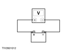
| A2: CHECK THE BATTERY VOLTAGE |
| | 1 Check the battery. Refer to Section 414-00. |
| | Is the battery OK? Yes No CHARGE or INSTALL a new battery as required. Refer to Section 414-00. TEST the system for normal operation. |
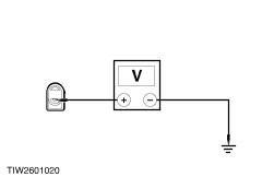
| A3: CHECK SWITCHED POWER SUPPLY TO THE SOLENOID |
| | 1 Disconnect Solenoid single pin. |
| | 2 Ignition switch in position III. |
| | 3 Measure the voltage between the starter motor solenoid connector single pin, circuit 50 (GY/BK) and ground when the starter is operated. |
| | Is the voltage greater than 10 volts? Yes No |
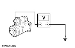
| A4: CHECK B+ TO THE STARTER |
| | 1 Ignition switch in position 0. |
| | 2 Measure the voltage between the starter motor terminal B, circuit 30 (RD) and ground. |
| | Is the voltage greater than 10 volts? Yes No REPAIR circuit 30 (RD). TEST the system for normal operation. |
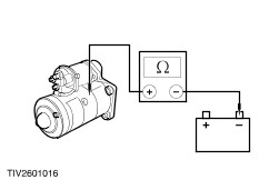
| A5: CHECK THE STARTER GROUND CIRCUIT |
| | 1 Measure the resistance between the starter motor casing and negative (-) battery terminal. |
| | Is the resistance less than 5 ohms? Yes INSTALL a new starter motor. TEST the system for normal operation. No CLEAN and REPAIR grounds as required. TEST the system for normal operation. |
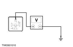
| A6: CHECK B+ TO STARTER RELAY |
| | 1 Disconnect Starter relay. |
| | 2 Measure the voltage between the starter relay connector pin 5, circuit 30 (RD) and ground. |
| | Is the voltage greater than 10 volts? Yes No REPAIR circuit 30 (RD). TEST the system for normal operation. |
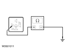
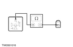
| A7: CHECK RELAY GROUND CIRCUIT |
| | 1 Measure the resistance between the starter relay connector pin 1, circuit 31 (BK) and ground. |
| | Is the resistance less than 5 ohms? Yes No REPAIR circuit 31 (BK). TEST the system for normal operation. |
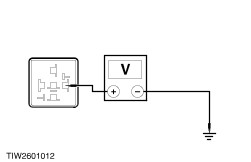
| A8: CHECK RELAY SWITCHING CIRCUIT |
| | 1 Ignition switch in position III. |
| | 2 Measure the voltage between the starter relay connector pin 2, circuit 50 (GY) and ground. |
| | Is the voltage greater than 10 volts? Yes No |
| A9: CHECK FUSE 40 (60A) |
| | 1 CHECK Fuse 40 (60A). |
| | Is the fuse OK? Yes No INSTALL a new fuse 40 (60A). TEST the system for normal operation. If fuse fails again GO to A15. |
| A10: CHECK CIRCUIT 30 (RD) CONTINUITY |
| | 1 Disconnect Ignition switch. |
| | 2 Remove the fuse 40 (60A). |
| | 3 Measure the resistance between the fuse 40 connector pin 1, circuit 30 (RD) and ignition switch connector pin 4, circuit 30 (RD). |
| | Is the resistance less than 5 ohms? Yes No REPAIR circuit 30 (RD). TEST the system for normal operation. |
| A11: CHECK THE IGNITION SWITCH |
| | 1 Ignition switch in position III. |
| | 2 Measure the resistance between pin 4 and pin 3 of the ignition switch connector. |
| | Is the resistance less than 5 ohms? Yes No INSTALL a new ignition switch. TEST the system for normal operation. |
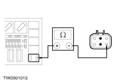
| A12: CHECK CIRCUIT 50 (GY) CONTINUITY |
| | 1 Ignition switch in position 0. |
| | 2 Measure the resistance between the ignition switch connector pin 3, circuit 50 (GY) and the starter relay connector pin 2, circuit 50 (GY). |
| | Is the resistance less than 5 ohms? Yes RECONNECT the ignition switch. GO to A8. No REPAIR circuit 50 (GY). TEST the system for normal operation. |
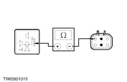
| A13: CHECK THE CONTINUITY OF CIRCUIT 50 (GY/BK) |
| | 1 Measure the resistance between the starter motor solenoid connector, circuit 50 (GY/BK) and starter relay connector pin 3, circuit 50 (GY/BK). |
| | Is the resistance less than 5 ohms? Yes No REPAIR circuit 50 (GY/BK). TEST the system for normal operation. |
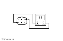
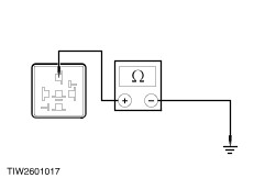
| A14: CHECK CIRCUIT 50 (GY/BK) FOR SHORT TO GROUND |
| | 1 Measure the resistance between the starter relay connector pin 3, circuit 50 (GY/BK) and ground. |
| | Is the resistance less than 5 ohms? Yes INSTALL a new starter relay. TEST the system for normal operation. No REPAIR circuit 50 (GY/BK). TEST the system for normal operation. |
| A15: CHECK CIRCUIT 30 (RD) FOR SHORT TO GROUND |
| | 1 Remove fuse 36 (60A). |
| | 2 Measure the resistance between fuse 36 connector pin 1, circuit 30 (RD) and ground. |
| | Is the resistance greater than 10,000 ohms? Yes No REPAIR circuit 30 (RD). TEST the system for normal operation. |
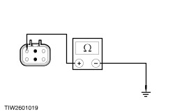
| A16: CHECK CIRCUIT 50 FOR SHORT TO GROUND |
| | 1 Disconnect Ignition switch. |
| | 2 Measure the resistance between the ignition switch connector pin 3, citcuit 50 (GY) and ground. |
| | Is the resistance greater than 10,000 ohms? Yes No REPAIR circuit 50 (GY). TEST the system for normal operation. |