| Assembly Special Tool(s) | | Installer, Rear Hub Bearing Cone/Oil Seal 205-296 (15-085) | | | Compressor, Valve Spring 303-060 (21-024) | | | Adapter for 303-060 303-060-02 (21-024-02) | | | Adapter for 303-060 303-060-07 (21-024-07) | | | Installer, Halfshaft Oil Seal 308-039 (16-018) | | | Installer, Input Shaft Bearing Cone 308-041 (16-020) | | | Installer, Extension Housing Bushing/Oil Seal 308-045 (16-015) | General Equipment Press Dial indicator gauge Magnetic base for dial indicator gauge Auxiliary plug M8 x 50 mm bolt Center punch Materials Name Specification Universal sealer (Hylomar) ESEE-M4G1008-A Silicon sealer WSE - M4G323 - A4 Sealant, transmission housing WSK - M2G348 - A5 Transmission fluid WSD - M2C200 - C High-temperature grease ESDM-1C220-A Assembly All vehicles | | -
Clean and check all parts carefully before reassembly. | | | -
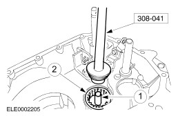
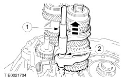
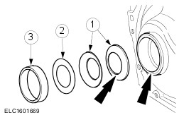
CAUTION:Install the output shaft roller bearings with the inscribed side facing upwards. Install the output shaft roller bearing and the bearing outer race with the special tool. - Install the oil thrower.
- Install the output shaft roller bearing.
| | | -
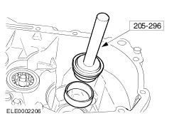
Install the differential bearing outer race using the special tool. | | | -
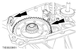
Install the differential assembly and permanent magnet. | | | -
Fit the reverse idler gear. | | | -
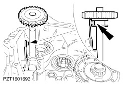
Install the selector shaft with the shift locking plate. | | | -
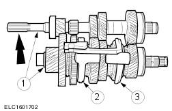
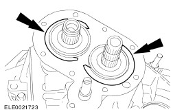
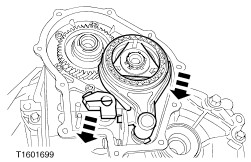
Prepare input and output shaft for installation. - Engage the input shaft and output shaft.
- Position the 1st/2nd gear selector fork.
- Position the 3rd/4th gear selector fork.
| | | -
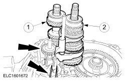
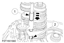
NOTE:Attach a rubber strap to the auxiliary selector shaft to ease assembly. Install the input and output shafts. - Insert the input shaft to a depth of approx. 50 mm and move slightly to one side.
- Insert the output shaft level with the input shaft and engage the gear wheels again.
- Install the input and output shafts.
| | | -
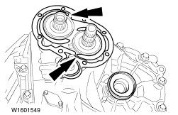
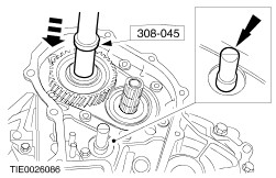
NOTE:Replace the lower snap ring. Install the selector shaft guide sleeve and lower snap ring. - Install the selector shaft guide sleeve.
- Install the lower snap ring.
| | | -
NOTE:Replace the upper snap ring. Attach the upper snap ring for the selector shaft guide sleeve. - Lift the guide sleeve.
- Install the upper snap ring.
| | | -
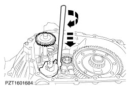
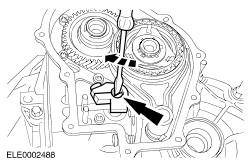
Switch the inner gearshift linkage to fifth gear. - Turn the auxiliary selector shaft clockwise until the reverse gear/5th gear shift gate is reached, then press downwards.
| | | -
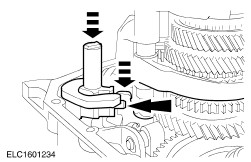
Install a 3.8 mm measuring shim and secure with a blow using a center punch. - Transmission housing
- Measuring shim
- Bearing outer race
| | | -
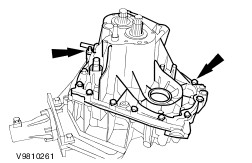
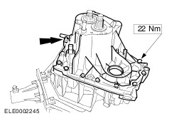
CAUTION:On transmissions without liquid sealers, the transmission gasket must be in place for the following measurement. NOTE:Thoroughly clean the transmission housing mating faces. Assemble the transmission housing. - Insert the auxiliary plugs.
- Turn the transmission through 180 degrees.
| | | -
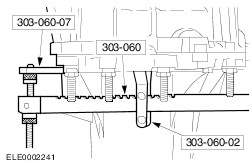
Attach the special tools. - Remove the auxiliary plugs.
| | | -
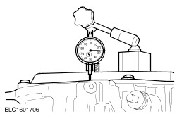
Prepare the differential for measuring. - Turn the differential approx. ten times to settle the bearings.
- Preload the dial indicator gauge to at least 1 mm.
| | | -
NOTE:Carry out the measurement three times and calculate the average value. NOTE:The adjusting shims are available from 0.1 mm to 1.1 mm in steps of 0.1 mm. Measure the differential end float. - Raise the differential assembly using the special tool.
- Note the resulting measurement (e.g. 0.73 mm).
| | | -
Calculate the required adjustment shim thickness. - The adjusting shim thickness is 0.5 mm (rounded off to 0.51 mm)
| | | -
Separate the transmission housing sections. - Detach the dial indicator gauge with the magnetic base and the special tools.
- Insert the auxiliary plugs.
- Turn the transmission through 180 degrees.
| | | -
Using the special tool, remove the differential bearing outer race and the measuring shim. | | | -
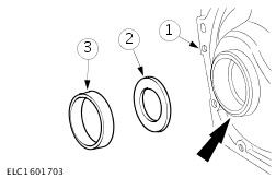
NOTE:The inner diameters of the Belleville washers contact one another. Install the adjusting shim determined and secure with a blow from a punch. - Install the Belleville washers.
- Install adjusting shim of determined thickness.
- Install the bearing outer race.
| | | -
On transmissions with a black end cover, apply transmission housing sealer evenly to the mating faces of the transmission housing sections. | | | -
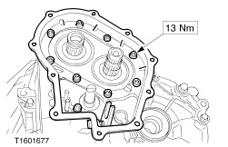
NOTE:On transmissions without liquid sealer note the installation position of the housing gasket. Assemble the transmission housing and tighten the bolts evenly. | | | -
NOTE:Replace the snap rings for the input and output shafts. NOTE:Use a wooden support. Carefully lift the input and output shafts and install the snap rings. | | | -
NOTE:Turn the snap rings so that they are located in the cut-outs in the gasket. NOTE:Replace the 5th gear housing gasket. Install the 5th gear housing gasket. | | | -
Attach the 5th gear housing. | | | -
Detach the transmission from the assembly stand. | | | -
NOTE:Secure the selector shaft to prevent it from turning in order to hold the reverse gear idler in the guide. NOTE:The transmission housing must not sit on the press table. Support the assembly on the splined clutch input shaft on the press table. Install the 5th gear wheel using the special tool and a suitable press. | | | -
Mount the transmission on the mounting stand. | | | -
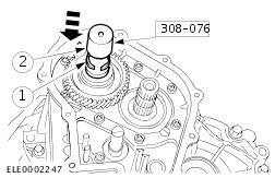
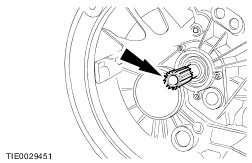
NOTE:Renew the snap ring for the 5th gear wheel. Attach the snap ring for the 5th gear wheel. - Fit the snap ring onto the special tool.
- Fit the special tool and push on the snap ring.
| | | -
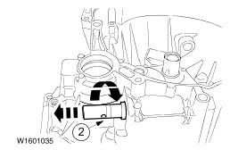
NOTE:Only perform the installation in neutral. Installation position for secondary selector shaft interlock. | | | -
NOTE:Only perform the installation in neutral. Install the selector shaft interlocks. | | | -
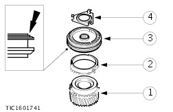
NOTE:Identification of gear synchronizer installation position. Assemble the 5th gear synchronizer unit. - 5th gear wheel
- Synchronizer ring
- Gear synchronizer
- Retaining plate
| | | -
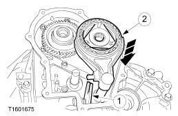
Install the 5th gear synchronizer unit and selector fork. - Swivel the drive plate upwards.
- Push on the 5th gear synchronizer unit it reaches the drive plate.
| | | -
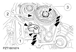
NOTE:Do not tighten the gear selector boss bolt at this stage. NOTE:Replace the snap ring for the 5th gear synchronizer unit. NOTE:Replace the gear selector boss retaining pin Install the 5th gear synchronizer unit and selector fork. - Install the gear selector boss.
- Move the selector boss and 5th gear synchronizer unit into position together.
- Attach the snap ring for the 5th gear synchronizer unit.
| | | -
NOTE:The 5th gear interlock mechanism must be installed. Engage fifth gear. - Press down the selector fork and gear selector boss together.
| | | -
Engage fifth gear. - Turn the selector shaft clockwise up to the stop.
| | | -
Engage fifth gear. - Turn the main selector shaft clockwise up to the stop and pull it out.
| | | -
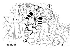
Adjust the gear selector boss. - Turn the selector shaft clockwise and press it down.
- Raise the gear selector boss to eliminate the end float.
- Tighten the bolt in this position.
| | | -
On transmissions with a black end cover, apply end cover sealer evenly to the mating faces of the end cover. | | | -
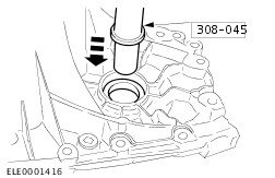
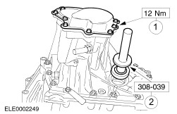
Install the 5th gear housing end cover and install the input shaft oil seal using the special tool. - Install the 5th gear housing end cover with gasket.
- Push in the input shaft oil seal until it engages audibly.
- Insert the auxiliary plugs.
| Vehicles built from 08/1999 | | -
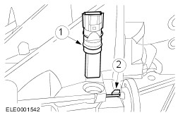
Install the vehicle speed sensor (VSS). - Install the VSS.
- Install the retaining pin.
| Vehicles built up to 08/1999 | | -
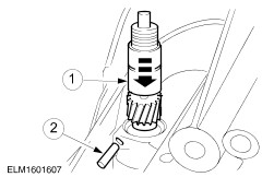
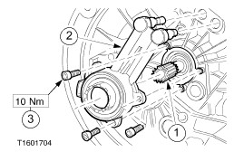
Fit the speedometer drive pinion. - Position the speedometer drive pinion.
- Install the retaining pin.
| | | -
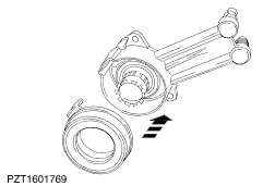
Install the thrust bearing. | All vehicles | | -
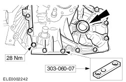
CAUTION:Wrap the input shaft splines with adhesive tape to protect the input shaft oil seal. Position the input shaft oil seal. | | | -
CAUTION:Do not coat the clutch slave cylinder with high-temperature grease. Fit the clutch slave cylinder. - Tighten the bolts evenly, pressing the input shaft oil seal into the transmission housing.
| | | -
Remove the adhesive tape from the input shaft splines. | | | -
Coat the input shaft splines lightly with grease. | Vehicles built up to 08/1999 | | -
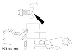
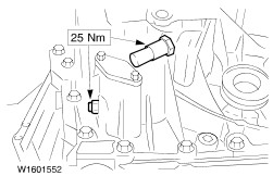
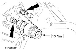
CAUTION:The preload valve will be damaged if the specified torque is exceeded. NOTE:Inspect the seal, renew as necessary. Fit the preload valve. - Tighten the bleed nipple and push on the protective cap.
| All vehicles |