| Diagnosis and Testing Refer to Wiring Diagrams Section 501-16, for schematic and connector information. Special Tool(s) | | Terminal Probe Kit 29-011 A | Inspection and Checking - Verify the customer concern.
- Visually check the following electrical or mechanical causes for the concern:
Visual Inspection Chart | Mechanical | Electrical | - Wiper blade(s)
- Wiper arm pivot shaft
- Windshield washer fluid reservoir
- Hose(s)
- Nozzles
| - Fuse(s)
- Connectors
- Wiring harness
- Washer system pump(s)
- Wiper motor(s)
| - Resolve any obvious causes or concerns found during the visual inspection before carrying out any further tests.
- If the concern persists, check the symptoms and continue with the symptom chart.
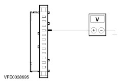
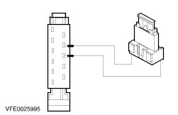
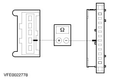
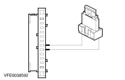
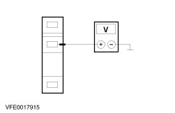
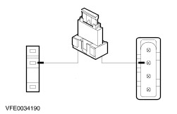
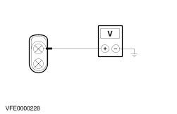
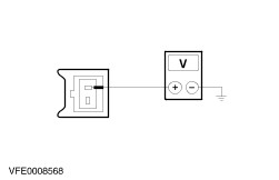
Symptom Chart Symptom Chart | Symptom | Possible Sources | Action | | Wipers inoperative | * Fuse * Circuit(s) * Multifunction switch * Tailgate contact plate * Windshield wiper motor * Rear window wiper motor * Central junction box (CJB) | * | | Brief wipe is inoperative (slow wipe OK) | * Wash/wipe system switch | * RENEW the wash/wipe system switch. CHECK the operation of the system. | | Wipers are continuously switched on (ignition on) | * Circuit(s) * Multifunction switch * Windshield wiper motor * Rear window wiper motor * Generic electronic module (GEM) | * | | Slow or fast wipe speed inoperative (intermittent mode OK) | * Circuit(s) * Multifunction switch * Windshield wiper motor | * | | Intermittent wipe mode inoperative (slow and fast wipe speed OK) | * Circuit(s) * Multifunction switch * Generic electronic module (GEM) | * | | Windshield wipers inoperative when washer system is actuated | * Circuit(s) * Multifunction switch * Generic electronic module (GEM) | * | | Windshield wipers do not return to park position after switching off | * Circuit(s) * Multifunction switch * Windshield wiper motor * Generic electronic module (GEM) | * | | Washer system pump inoperative | * Circuit(s) * Washer pump motor * Multifunction switch | * | | Washer fluid level warning lamp not working properly | * Circuit(s) * Washer fluid level switch * Instrument cluster | * | System Check NOTE:Use a digital multimeter for all electrical measurements. | PINPOINT TEST A : WIPERS INOPERATIVE | | TEST CONDITIONS | DETAILS/RESULTS/ACTIONS | | A1: CHECK FUSE F12 (CJB) | | | 1 Ignition switch in position 0. | | | 2 CHECK fuse F12 (CJB) (20 A). | | | Is the fuse OK.? Yes No RENEW fuse F12 (20 A) and check the operation of the system. If the fuse blows again, LOCATE and RECTIFY the short to ground using the Wiring Diagrams. CHECK the operation of the system. | | A2: CHECK THE VOLTAGE AT FUSE F12 | | | 1 Ignition switch in position 0. | | | 2 Connect fuse F12 (CJB). | | | 3 Ignition switch in position II. | | | 4 Measure the voltage between fuse F12 (20 A) and ground. | | | Does the meter display battery voltage? Yes No CHECK and if necessary RENEW the CJB. CHECK the operation of the system. | | A3: CHECK THE CIRCUIT BETWEEN FUSE F12 AND THE MULTIFUNCTION SWITCH | | | 1 Ignition switch in position 0. | | | 2 Disconnect multifunction switch from connector C65b. | | | 3 Ignition switch in position II. | | | 4 Measure the voltage between the multifunction switch, connector C65b, pin 7, circuit 14-AK19 (VT/OG), wiring harness side and ground. | | | Does the meter display battery voltage? Yes No LOCATE and RECTIFY the break in the circuit between fuse F12 and the multifunction switch using the Wiring Diagrams. CHECK the operation of the system. | | A4: CHECK THE MULTIFUNCTION SWITCH | | | 1 Ignition switch in position 0. | | | 2 Use a fused test cable (20 A) to bridge the wash/wipe system switch, connector C65b, pin 7, circuit 14-AK19 (VT/OG) and pin 3, circuit 14S-AK10 (VT/BK), wiring harness side. | | | 3 Use a fused test cable (20 A) to bridge the wash/wipe system switch, connector C65b, pin 7, circuit 14-AK19 (VT/OG) and pin 8, circuit 32-AK28 (WH/RD), wiring harness side. | | | 4 Ignition switch in position II. | | | Is the windshield wiper motor and/or the rear window wiper motor running? Yes Both wiper motors running: RENEW the multifunction switch. CHECK the operation of the system. No - Windshield wipers inoperative: GO to A6. - Rear window wiper inoperative, vehicles built up to 09.00: GO to A8. - Rear window wiper inoperative, vehicles built from 09.00: GO to A5. | | A5: CHECK VOLTAGE AT THE REAR WINDOW WIPER MOTOR | | | 1 Connect multifunction switch to connector C65b. | | | 2 Disconnect rear window wiper motor from connector C344. | | | 3 Ignition switch in position II. | | | 4 SWITCH ON rear window wiper. | | | 5 Measure the voltage between the rear window wiper motor, connector C344, pin 2, circuit 32-AK28 (WH/RD), wiring harness side and ground. | | | Does the meter display battery voltage? Yes CHECK the ground connection of the rear window wiper motor housing. CHECK the operation of the system. If the concern persists, RENEW the wiper motor. CHECK the operation of the system. No LOCATE and RECTIFY the break in the circuit between the multifunction switch and the rear window wiper motor using the Wiring Diagrams. CHECK the operation of the system. | | A6: CHECK VOLTAGE AT THE WINDSHIELD WIPER MOTOR | | | 1 Connect multifunction switch to connector C65b. | | | 2 Disconnect windshield wiper motor from connector C43. | | | 3 Ignition switch in position II. | | | 4 SWITCH ON slow wipe speed. | | | 5 Measure the voltage between the windshield wiper motor, connector C43, pin 4, circuit 14S-AK10 (VT/BK), wiring harness side and ground. | | | Does the meter display battery voltage? Yes No LOCATE and RECTIFY the break in the circuit between the multifunction switch and the windshield wiper motor using the Wiring Diagrams. CHECK the operation of the system. | | A7: CHECK THE GROUND CONNECTION OF THE WINDSHIELD WIPER MOTOR | | | 1 Ignition switch in position 0. | | | 2 Measure the resistance between the windshield wiper motor, connector C43, pin 1, circuit 31-AK8 (BK), wiring harness side and ground. | | | Is the resistance less than 2 Ohm? Yes RENEW the windshield wiper motor. CHECK the operation of the system. No LOCATE and RECTIFY the break in the circuit between the windshield wiper motor and soldered connection S65 using the Wiring Diagrams. CHECK the operation of the system. | | A8: CHECK THE VOLTAGE AT THE TAILGATE CONTACT PLATE | | | 1 Connect multifunction switch to connector C65b. | | | 2 Disconnect tailgate contact plate from connector C312a. | | | 3 Ignition switch in position II. | | | 4 SWITCH ON rear window wiper. | | | 5 Measure the voltage between the tailgate contact plate, connector C312a, pin 3, circuit 32-AK28 (WH/RD), wiring harness side and ground. | | | Does the meter display battery voltage? Yes No LOCATE and RECTIFY the break in the circuit between the multifunction switch and the tailgate contact plate using the Wiring Diagrams. If necessary RENEW the tailgate contact plate. CHECK the operation of the system. | | A9: CHECK THE VOLTAGE AT THE TAILGATE CONTACT PLATE | | | 1 Use a fused test cable (20 A) to bridge the tailgate contact plate between connector C312a, pin 3, circuit 32-AK28 (WH/RD), wiring harness side and connector C312b, circuit 32-AK28 (WH/RD), wiring harness side. | | | 2 Ignition switch in position II. | | | 3 SWITCH ON rear window wiper. | | | 4 Check the rear window wiper. | | | Is the rear window wiper motor operative? Yes RENEW the tailgate contact plate. CHECK the operation of the system. No | | A10: MEASURE THE VOLTAGE AT THE REAR WINDOW WIPER MOTOR | NOTE:Connect a fused test cable between connector C312a, pin 3, circuit 32-AK28 (WH/RD) and connector C312b, circuit 32-AK28 (WH/RD). | | | 1 Ignition switch in position 0. | | | 2 Disconnect rear window wiper motor from connector C344. | | | 3 Ignition switch in position II. | | | 4 SWITCH ON rear window wiper. | | | 5 Measure the voltage between the rear window wiper motor, connector C344, pin 2, circuit 32-AK28 (WH/RD), wiring harness side and ground. | | | Does the meter display battery voltage? Yes CHECK the ground connection of the rear window wiper motor housing. CHECK the operation of the system. If the concern persists, RENEW the rear window wiper motor. CHECK the operation of the system. No LOCATE and RECTIFY the break in the circuit between the tailgate contact plate and the rear window wiper motor using the Wiring Diagrams. CHECK the operation of the system. | | PINPOINT TEST B : WIPERS ARE CONTINUOUSLY SWITCHED ON (IGNITION ON) | | TEST CONDITIONS | DETAILS/RESULTS/ACTIONS | | B1: CHECK THE MULTIFUNCTION SWITCH | | | 1 Ignition switch in position 0. | | | 2 Disconnect multifunction switch from connector C65b. | | | 3 Ignition switch in position II. | | | 4 Check the defective wipers. | | | Does the defective wiper motor run continuously? Yes - Windshield wipers run at fast wipe speed: GO to B2. - Rear window wiper, vehicles built up to 09.00: GO to B6. - Rear window wiper, vehicles built form 09.00: GO to B5. No - Windshield wipers (fast wipe speed): RENEW the multifunction switch. CHECK the operation of the system. - Windshield wipers (slow wipe speed): GO to B3. - Rear window wiper: RENEW the multifunction switch. CHECK the operation of the system. | | B2: CHECK CIRCUIT 14S-AK11 (VT/OG) FOR WINDSHIELD WIPER MOTOR FOR SHORT TO BATTERY VOLTAGE | | | 1 Ignition switch in position 0. | | | 2 Disconnect windshield wiper motor from connector C43. | | | 3 Ignition switch in position II. | | | 4 Measure the voltage between multifunction switch, connector C65b, pin 5, circuit 14S-AK11 (VT/OG), wiring harness side and ground. | | | Does the meter display battery voltage? Yes LOCATE AND RECTIFY the short to battery voltage in circuit 14S-AK11 (VT/OG) using the Wiring Diagrams. CHECK the operation of the system. No RENEW the windshield wiper motor. CHECK the operation of the system. | | B3: CHECK THE VOLTAGE AT THE MULTIFUNCTION SWITCH | | | 1 Measure the voltage between the multifunction switch, connector C65b, pin 9, circuit(s) 31S-AK19 (BK/RD)/31S-AK15 (BK/RD), wiring harness side and ground. | | | Does the meter display battery voltage? Yes No RENEW the multifunction switch. CHECK the operation of the system. | | B4: CHECK THE WINDSHIELD WIPER MOTOR | NOTE:The windshield wiper motor must be in the park position. | | | 1 Ignition switch in position 0. | | | 2 Disconnect generic electronic module (GEM) from connector C212a. | | | 3 Ignition switch in position II. | | | 4 Measure the voltage between the generic electronic module (GEM), connector C212a, pin 7, circuit 31S-AK9 (BK/OG), wiring harness side and ground. | | | Does the meter display battery voltage? Yes RENEW the windshield wiper motor. CHECK the operation of the system. No RENEW the generic electronic module (GEM). CHECK the operation of the system. | | B5: CHECK CIRCUIT 32-AK28 (WH/RD) FOR SHORT TO BATTERY VOLTAGE | | | 1 Ignition switch in position 0. | | | 2 Disconnect rear window wiper motor from connector C344. | | | 3 Ignition switch in position II. | | | 4 Measure the voltage between the rear window wiper motor, connector C344, pin 2, circuit 32-AK28 (WH/RD), wiring harness side and ground. | | | Does the meter display battery voltage? Yes LOCATE and RECTIFY the short to battery voltage in the circuit between the multifunction switch and the rear window wiper motor using the Wiring Diagrams. CHECK the operation of the system. No RENEW the rear window wiper motor. CHECK the operation of the system. | | B6: CHECK CIRCUIT 32-AK28 (WH/RD) BETWEEN THE MULTIFUNCTION SWITCH AND THE TAILGATE CONTACT PLATE FOR SHORT TO BATTERY VOLTAGE | | | 1 Measure the voltage between the tailgate contact plate, connector C312a, pin 3, circuit 32-AK28 (WH/RD), wiring harness side and ground. | | | Does the meter display battery voltage? Yes LOCATE and RECTIFY the short to battery voltage in the circuit between the multifunction switch and the tailgate contact plate using the Wiring Diagrams. CHECK the operation of the system. No | | B7: CHECK CIRCUIT 32-AK28 (WH/RD) BETWEEN THE TAILGATE CONTACT PLATE AND THE REAR WINDOW WIPER MOTOR FOR SHORT TO BATTERY VOLTAGE | | | 1 Measure the voltage between the rear window wiper motor, connector C344, pin 2, circuit 32-AK28 (WH/RD), wiring harness side and ground. | | | Does the meter display battery voltage? Yes LOCATE and RECTIFY the short to battery voltage in the circuit between the tailgate contact plate and the rear window wiper motor using the Wiring Diagrams. CHECK the operation of the system. No RENEW the rear window wiper motor. CHECK the operation of the system. | | PINPOINT TEST C : SLOW OR FAST WIPE SPEED INOPERATIVE (INTERMITTENT MODE OK) | | TEST CONDITIONS | DETAILS/RESULTS/ACTIONS | | C1: DETERMINE CAUSE OF FAULT | | | 1 Ignition switch in position II. | | | 2 SWITCH THROUGH ALL WIPE SPEEDS (INTERMITTENT/SLOW/FAST). | | | 3 CHECK windshield wipers. | | | Are windshield wipers operative in intermittent mode? Yes - Slow wipe speed inoperative: RENEW the multifunction switch. CHECK the operation of the system. - Fast wipe speed inoperative. GO to C2. No - Slow wipe speed inoperative GO to Pinpoint Test D. - Slow wipe speed inoperative: GO to C4. | | C2: CHECK VOLTAGE AT THE WINDSHIELD WIPER MOTOR | | | 1 Ignition switch in position 0. | | | 2 Disconnect windshield wiper motor from connector C43. | | | 3 Ignition switch in position II. | | | 4 SWITCH ON fast wipe speed. | | | 5 Measure the voltage between the windshield wiper motor, connector C43, pin 5, circuit 14S-AK11 (VT/OG), wiring harness side and ground. | | | Does the meter display battery voltage? Yes RENEW the windshield wiper motor. CHECK the operation of the system. No | | C3: CHECK THE MULTIFUNCTION SWITCH | | | 1 Ignition switch in position 0. | | | 2 Disconnect multifunction switch from connector C65b. | | | 3 Use a fused test cable (20 A) to bridge the wash/wipe system switch, connector C65b, pin 7, circuit 14-AK19 (VT/OG) and pin 5, circuit 14S-AK11 (VT/OG), wiring harness side. | | | 4 Ignition switch in position II. | | | Does the windshield wiper motor run at fast wipe speed? Yes RENEW the multifunction switch. CHECK the operation of the system. No LOCATE and RECTIFY the break in the circuit between the multifunction switch and the windshield wiper motor using the Wiring Diagrams. CHECK the operation of the system. | | C4: CHECK VOLTAGE AT THE WINDSHIELD WIPER MOTOR | | | 1 Ignition switch in position 0. | | | 2 Disconnect windshield wiper motor from connector C43. | | | 3 Ignition switch in position II. | | | 4 SWITCH ON slow wipe speed. | | | 5 Measure the voltage between the windshield wiper motor, connector C43, pin 4, circuit 14S-AK10 (VT/BK), wiring harness side and ground. | | | Does the meter display battery voltage? Yes RENEW the windshield wiper motor. CHECK the operation of the system. No | | C5: CHECK THE MULTIFUNCTION SWITCH | | | 1 Ignition switch in position 0. | | | 2 Disconnect multifunction switch from connector C65b. | | | 3 Use a fused test cable (20 A) to bridge the wash/wipe system switch, connector C65b, pin 7, circuit 14-AK19 (VT/OG) and pin 3, circuit 14S-AK10 (VT/BK), wiring harness side. | | | 4 Ignition switch in position II. | | | Does the windshield wiper motor run at slow wipe speed? Yes RENEW the multifunction switch. CHECK the operation of the system. No LOCATE and RECTIFY the break in the circuit between the multifunction switch and the windshield wiper motor using the Wiring Diagrams. CHECK the operation of the system. | | PINPOINT TEST D : INTERMITTENT WIPE MODE INOPERATIVE (SLOW AND FAST WIPE SPEED OK) | | TEST CONDITIONS | DETAILS/RESULTS/ACTIONS | | D1: CHECK THE MULTIFUNCTION SWITCH | | | 1 Ignition switch in position 0. | | | 2 Disconnect multifunction switch from connector C65b. | | | 3 Use a fused test cable (20 A) to bridge the wash/wipe system switch, connector C65b, pin 9, circuit 31S-AK19 (BK/RD) and pin 3, circuit 14S-AK10 (VT/BK), wiring harness side. | | | 4 Use a fused test cable (20 A) to bridge the wash/wipe system switch, connector C65b, pin 7, circuit 14-AK19 (VT/OG) and pin 10, circuit 14S-AK14 (VT/BK), wiring harness side. | | | 5 Ignition switch in position II. | | | Do windshield wipers run in intermittent mode? Yes RENEW the multifunction switch. CHECK the operation of the system. No | | D2: READ OUT THE FAULT MEMORY | | | 1 Ignition switch in position 0. | | | 2 Connect multifunction switch to connector C65b. | | | 3 Connect the diagnostic tool. | | | 4 Check the GEM module using WDS. | | | Are any trouble codes (DTCs) displayed? Yes RECTIFY faults according to WDS instructions. CLEAR the fault memory and CHECK the operation of the system. No | | D3: CHECK THE VOLTAGE AT THE GENERIC ELECTRONIC MODULE (GEM) | | | 1 Disconnect generic electronic module (GEM) from connector C212a. | | | 2 Ignition switch in position II. | | | 3 Measure the voltage between the generic electronic module (GEM), connector C212a, pin 6, circuit 14-AK15 (VT/OG), wiring harness side and ground. | | | Does the meter display battery voltage? Yes No LOCATE and RECTIFY the break in the circuit between soldered connection S120 and the generic electronic module (GEM) using the Wiring Diagrams. CHECK the operation of the system. | | D4: CHECK CIRCUIT 14S-AK14 (VT/BK) BETWEEN THE MULTIFUNCTION SWITCH AND THE GENERIC ELECTRONIC MODULE (GEM) | | | 1 SWITCH ON intermittent wipe. | | | 2 Measure the voltage between the generic electronic module (GEM), connector C212a, pin 9, circuit 14S-AK14 (VT/BK), wiring harness side and ground. | | | Does the meter display battery voltage? Yes No LOCATE and RECTIFY the break in circuit 14S-AK14 (VT/BK) between the multifunction switch and the generic electronic module (GEM) using the Wiring Diagrams. CHECK the operation of the system. | | D5: CHECK THE GROUND CONNECTION OF THE GENERIC ELECTRONIC MODULE (GEM) | | | 1 Ignition switch in position 0. | | | 2 Disconnect generic electronic module (GEM) from connector C212b. | | | 3 Measure the resistance between the generic electronic module (GEM), connector C212b, pin 12, circuit 31-DA20 (BK), wiring harness side and ground. | | | Is the resistance less than 2 Ohm? Yes RENEW the generic electronic module (GEM). CHECK the operation of the system. No LOCATE and RECTIFY the break in circuit 31-DA20 (BK) between the generic electronic module (GEM) and soldered connection S65 using the Wiring Diagrams. CHECK the operation of the system. | | PINPOINT TEST E : WINDSHIELD WIPERS INOPERATIVE WHEN WASHER SYSTEM IS ACTUATED | | TEST CONDITIONS | DETAILS/RESULTS/ACTIONS | | E1: DETERMINE CAUSE OF FAULT | | | 1 Determine cause of fault. | | | Are windshield wipers inoperative when windshield washer system is actuated? Yes Windshield wipers inoperative: GO to E4. No Windshield wash/wipe function inoperative: GO to E2. | | E2: CHECK THE MULTIFUNCTION SWITCH | | | 1 SWITCH ON hazard warning lights. | | | 2 Check hazard warning lights | | | Do the hazard warning lights operate correctly? Yes RENEW the multifunction switch. CHECK the operation of the system. No | | E3: CHECK GROUND CONNECTION OF MULTIFUNCTION SWITCH | | | 1 Ignition switch in position 0. | | | 2 Disconnect multifunction switch from connector C65a. | | | 3 Measure the resistance between multifunction switch, connector C65a, pin 8, circuit 31-LE29 (BK), wiring harness side and ground. | | | Is the resistance less than 2 Ohm? Yes RENEW the multifunction switch. CHECK the operation of the system. No LOCATE and RECTIFY the break in circuit 31-LE29 (BK), between the multifunction switch and soldered connection S65, using the Wiring Diagrams. CHECK the operation of the system. | | E4: DETERMINE CAUSE OF FAULT | | | 1 Ignition switch in position II. | | | 2 SWITCH ON slow wipe speed. | | | 3 Check the windshield wipers. | | | Does the windshield wiper motor run at slow wipe speed? Yes No | | E5: CHECK CIRCUIT 32-AK14 (WH/GN) FOR OPEN CIRCUIT | | | 1 Ignition switch in position 0. | | | 2 Disconnect generic electronic module (GEM) from connector C212a. | | | 3 Ignition switch in position II. | | | 4 Measure the voltage between the generic electronic module (GEM), connector C212a, pin 4, circuit 32-AK14 (WH/GN), wiring harness side and ground. | | | Does the meter display battery voltage? Yes CHECK the generic electronic module (GEM) using WDS and RENEW if necessary. CHECK the operation of the system. No LOCATE and RECTIFY the break in circuit 32-AK14 (WH/GN) between the multifunction switch and the generic electronic module (GEM) using the Wiring Diagrams. CHECK the operation of the system. | | PINPOINT TEST F : WIPERS DO NOT RETURN TO PARK POSITION AFTER SWITCHING OFF | | TEST CONDITIONS | DETAILS/RESULTS/ACTIONS | | F1: DETERMINE EQUIPMENT LEVEL OF VEHICLE | | | 1 Determine the equipment level of the vehicle. | | | Is the vehicle equipped with a rear window wiper? Yes No | | F2: DETERMINE CAUSE OF FAULT | | | 1 Determine cause of fault. | | | Does the rear window wiper return to the park position after switching off? Yes Windshield wipers do not return to park position after switching off: GO to F3. No - Rear window wiper does not return to the original position, before 09/2000: GO to F9. - Rear window wiper does not return to the original position, from 09/2000: GO to F12. | | F3: CHECK INTERMITTENT WIPE | | | 1 Ignition switch in position II. | | | 2 SWITCH ON intermittent wipe. | | | 3 Check windshield wipers. | | | Are the windshield wipers operative in intermittent mode? Yes No | | F4: CHECK THE MULTIFUNCTION SWITCH | | | 1 SWITCH ON windshield wipers. | | | 2 SWITCH OFF the ignition during the wipe cycle, (wipers not in park position). | | | 3 SWITCH OFF windshield wipers. | | | 4 Disconnect multifunction switch from connector C65b. | | | 5 Connect a fused jumper wire (20 A) to the multifunction switch, connector C65b, between pin 3, circuit 14S-AK10 (VT/BK) and pin 2, circuit 31S-AK15 (BK/RD), wiring harness side. | | | 6 Ignition switch in position II. | | | Do the wipers return to the park position? Yes RENEW the multifunction switch. CHECK the operation of the system. No | | F5: CHECK CIRCUIT 31S-AK15 (BK/RD) BETWEEN PIN 2 AND PIN 9 OF THE MULTIFUNCTION SWITCH | | | 1 Ignition switch in position 0. | | | 2 Connect a fused jumper wire (20 A) to the multifunction switch, connector C65b, between pin 3, circuit 14S-AK10 (VT/BK) and pin 9, circuit 31S-AK19 (BK/RD)/31S-AK15 (BK/RD), wiring harness side. | | | 3 Ignition switch in position II. | | | Do the wipers return to the park position? Yes LOCATE and RECTIFY the break in circuit 31-AK15 (BK/RD) at multifunction switch, connector C65b, between pin 2 and pin 9 using the Wiring Diagrams. CHECK the operation of the system. No | | F6: CHECK VOLTAGE AT THE WINDSHIELD WIPER MOTOR | | | 1 Ignition switch in position 0. | | | 2 Disconnect windshield wiper motor from connector C43. | | | 3 Ignition switch in position II. | | | 4 Measure the voltage between the windshield wiper motor, connector C43, pin 3, circuit 14-AK8 (VT/BU), wiring harness side and ground. | | | Does the meter display battery voltage? Yes No LOCATE and RECTIFY the break in the circuit between soldered connection S120 and the windshield wiper motor using the Wiring Diagrams. CHECK the operation of the system. | | F7: CHECK THE CIRCUIT BETWEEN THE WINDSHIELD WIPER MOTOR AND THE GENERIC ELECTRONIC MODULE (GEM) | | | 1 Ignition switch in position 0. | | | 2 Disconnect generic electronic module (GEM) from connector C212a. | | | 3 Measure the resistance between the windshield wiper motor, connector C43, pin 2, circuit 31S-AK9 (BK/OG), wiring harness side and the generic electronic module (GEM), connector C212a, pin 7, circuit 31S-AK9 (BK/OG), wiring harness side. | | | Is the resistance less than 2 Ohm? Yes No LOCATE and RECTIFY the break in the circuit between the windshield wiper motor and the generic electronic module (GEM) using the Wiring Diagrams. CHECK the operation of the system. | | F8: CHECK THE GENERIC ELECTRONIC MODULE (GEM) | | | 1 Connect windshield wiper motor to connector C43. | | | 2 Connect a fused jumper lead (20 A)to the generic electronic module (GEM), connector C212a, between pin 7, circuit 31S-AK9 (BK/OG) and pin 8, circuit 31S-AK19 (BK/RD), wiring harness side. | | | 3 Ignition switch in position II. | | | Do the wipers return to the park position? Yes RENEW the generic electronic module (GEM). CHECK the operation of the system. No RENEW the windshield wiper motor. CHECK the operation of the system. | | F9: CHECK VOLTAGE AT TAILGATE CONTACT PLATE | | | 1 Disconnect tailgate contact plate from connector C312a. | | | 2 Ignition switch in position II. | | | 3 Measure the voltage between the tailgate contact plate, connector C312a, pin 2, circuit 14-AK28 (VT/BU), wiring harness side and ground. | | | Does the meter display battery voltage? Yes No LOCATE and RECTIFY the break in circuit 14-AK28 (VT/BU) between soldered connection, S120 and the tailgate contact plate using the Wiring Diagrams. CHECK the operation of the system. | | F10: CHECK TAILGATE CONTACT PLATE | | | 1 Ignition switch in position 0. | | | 2 Disconnect tailgate contact plate from connector C312b. | | | 3 Use a fused test cable (20 A) to bridge the tailgate contact plate between connector C312a and connector C312b, pin 2, circuit 14-AK28 (WH/RD). | | | 4 Ignition switch in position II. | | | Does the rear window wiper return to the park position? Yes RENEW the tailgate contact plate. CHECK the operation of the system. No | | F11: CHECK THE VOLTAGE AT THE REAR WINDOW WIPER MOTOR, CIRCUIT 14-AK28 (VT/BU) | NOTE:The fused test cable between connector C312a and connector C312b, pin 2, circuit 14-AK28 (VT/BU) remains connected. | | | 1 Ignition switch in position 0. | | | 2 Disconnect rear window wiper motor from connector C344. | | | 3 Ignition switch in position II. | | | 4 Measure the voltage between the rear window wiper motor, connector C344, pin 1, circuit 14-AK28 (VT/BU), wiring harness side and ground. | | | Does the meter display battery voltage? Yes RENEW the rear window wiper motor. CHECK the operation of the system. No LOCATE and RECTIFY the break in circuit 14-AK28 (VT/BU) between the tailgate contact plate and the rear window wiper motor using the Wiring Diagrams. CHECK the operation of the system. | | F12: CHECK THE VOLTAGE AT THE REAR WINDOW WIPER MOTOR, CIRCUIT 14-AK28 (VT/BU) | | | 1 Ignition switch in position 0. | | | 2 Disconnect rear window wiper motor from connector C344. | | | 3 Ignition switch in position II. | | | 4 Measure the voltage between the rear window wiper motor, connector C344, pin 1, circuit 14-AK28 (VT/BU), wiring harness side and ground. | | | Does the meter display battery voltage? Yes RENEW the rear window wiper motor. CHECK the operation of the system. No LOCATE and RECTIFY the break in the circuit between soldered connection S120 and the rear window wiper motor using the Wiring Diagrams. CHECK the operation of the system. | | PINPOINT TEST G : WASHER SYSTEM PUMP INOPERATIVE | | TEST CONDITIONS | DETAILS/RESULTS/ACTIONS | | G1: DETERMINE CAUSE OF FAULT | | | 1 Determine cause of fault. | | | Is the front and rear washer function inoperative? Yes No - Rear only: RENEW the multifunction switch. CHECK the operation of the system. - Front only: GO to Pinpoint Test E. | | G2: CHECK THE VOLTAGE AT THE WASHER PUMP MOTOR | | | 1 Ignition switch in position 0. | | | 2 Disconnect washer pump motor from connector C121. | | | 3 Ignition switch in position II. | | | 4 Measure the voltage between the washer pump motor, connector C121, pin 1, circuit 32-AK34 (WH/BK), wiring harness side and ground. | | | Does the meter display battery voltage? Yes No LOCATE and RECTIFY the break in the circuit between the multifunction switch and the washer pump motor using the Wiring Diagrams. CHECK the operation of the system. | | G3: CHECK THE VOLTAGE AT THE WASHER PUMP MOTOR | | | 1 Measure the voltage between the washer pump motor, connector C121, pin 2, circuit 33-AK34 (YE/BK), wiring harness side and ground. | | | Does the meter display battery voltage? Yes RENEW the washer pump motor. CHECK the operation of the system. No | | G4: CHECK THE MULTIFUNCTION SWITCH | | | 1 Ignition switch in position 0. | | | 2 Disconnect multifunction switch from connector C65b. | | | 3 Measure the resistance between the multifunction switch, connector C65b, pin 1, circuit 33-AK34 (YE/BK), wiring harness side and the washer pump motor, connector C121, pin 2, wiring harness side. | | | Is the resistance less than 2 Ohm? Yes RENEW the multifunction switch. CHECK the operation of the system. No LOCATE and RECTIFY the break in the circuit between the multifunction switch and the washer pump motor using the Wiring Diagrams. CHECK the operation of the system. | |