
Five Hundred 2WD V6-3.0L VIN 1 (2006)
Parking Lamp: Initial Inspection and Diagnostic Overview
Principles of Operation
PRINCIPLES OF OPERATION
The smart junction box (SJB) monitors the headlamp switch position by sending multiple voltage reference signals to the headlamp switch. When the
headlamp switch is in any given position, that input signal is routed to ground.
When the SJB receives an input from the headlamp switch indicating a request for the parking lamps, the SJB energizes the parking lamp relay (internal
to the SJB), which supplies voltage to the exterior lamps.
Inspection and Verification
INSPECTION AND VERIFICATION
1. Verify the customer concern.
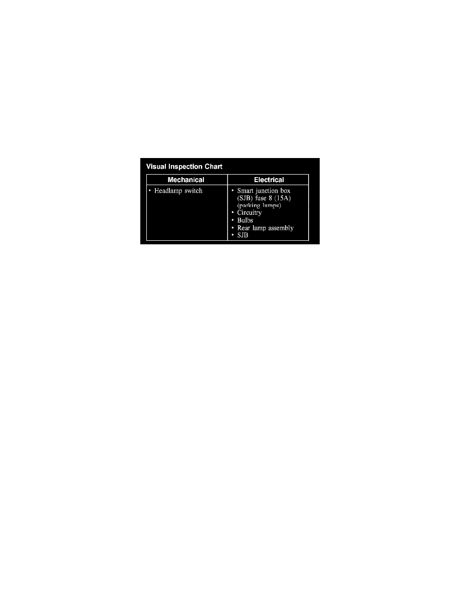
Visual Inspection Chart
2. Visually inspect for obvious signs of mechanical or electrical damage.
3. If an obvious cause for an observed or reported concern is found, correct the cause (if possible) before proceeding to the next step.
NOTE:
-
Make sure the headlamp switch is in the OFF position.
-
Make sure the multifunction switch is in the LOW BEAM position.
4. If the cause is not visually evident, connect the diagnostic tool to the data link connector (DLC) and select the vehicle to be tested from the
diagnostic tool menu. If the diagnostic tool does not communicate with the vehicle:
-
check that the program card is correctly installed.
-
check the connections to the vehicle.
-
check the ignition switch position.
5. If the diagnostic tool still does not communicate with the vehicle, refer to the diagnostic tool operating manual.
6. Carry out the diagnostic tool data link test. If the diagnostic tool responds with:
-
CAN circuit fault; all electronic control units no response/not equipped, refer to Information Bus (Module Communications Network).
-
No response/not equipped for SJB, refer to Body Control Systems (Multifunction Electronic Control Module).
-
System passed, retrieve and record the continuous diagnostic trouble codes (DTCs), erase the continuous DTCs and carry out the self-test
diagnostics for the SJB.
7. If the DTCs retrieved are related to the concern, go to the Smart Junction Box (SJB) Diagnostic Trouble Code (DTC) Index. See: Diagnostic
Trouble Code Descriptions
8. If no DTCs related to the concern are retrieved, GO to Symptom Chart. See: Symptom Related Diagnostic Procedures