
Five Hundred AWD V6-3.0L VIN 1 (2005)
Part 2
Removal and Installation
1. If equipped with adjustable pedals, make sure they are in the full forward position.
2. Remove the steering column.
3. Disconnect the electrical connectors from the brake pedal assembly.
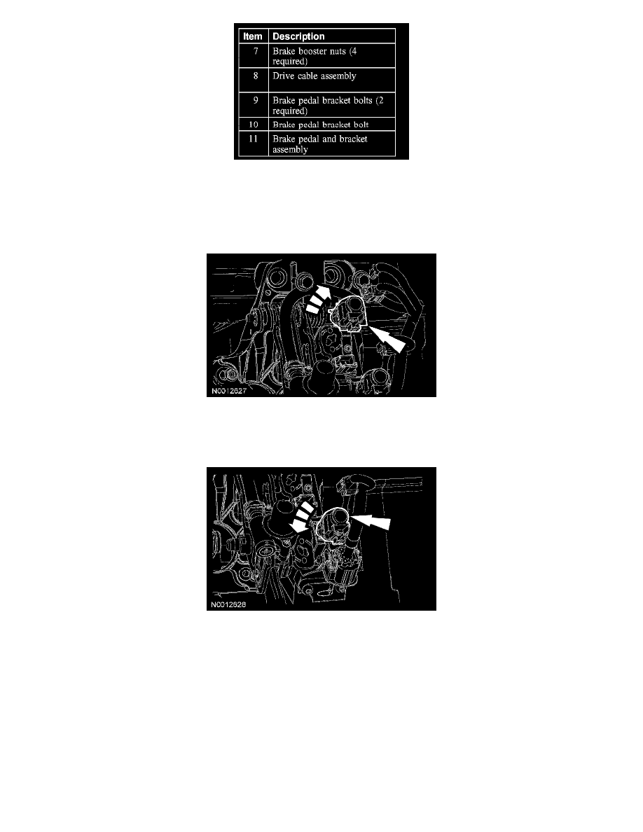
4. CAUTION: The brake pedal must be connected to the brake booster rod and in the at-rest position before removing or installing this
switch or damage to the switch will occur.
Remove the stoplamp switch.
5. CAUTION: The brake pedal must be connected to the brake booster rod and in the at-rest position before removing or installing this
switch or damage to the switch will occur.
If equipped, remove the speed control deactivator switch.
6. Remove the redundant self-locking clip cover and the self-locking clip.
7. Remove the booster rod and washer from the brake pedal.
8. Remove the 4 brake booster nuts.
-
To install, tighten to 25 Nm (18 lb-ft).
9. Position the brake booster forward enough to allow the brake booster studs to clear the brake pedal assembly.
10. Remove the lower brake pedal bracket bolt, under the accelerator pedal, from the brake pedal bracket assembly.
-
To install, tighten to 25 Nm (18 lb-ft).
11. Remove the upper 2 brake pedal bracket bolts from the brake pedal bracket assembly.