
Five Hundred AWD V6-3.0L VIN 1 (2005)
Catalytic Converter: Description and Operation
Catalyst and Exhaust Systems Overview
The catalytic converter and exhaust systems work together to control the release of harmful engine exhaust emissions into the atmosphere. The engine
exhaust gas consists mainly of nitrogen carbon dioxide (C02) and water vapor (H20). However~ it also contains carbon monoxide (CO) oxides of
nitrogen (NO) hydrogen (H) and various unburned hydrocarbons (HCs). CO NO and HCs are major air pollutants and their emission into the
atmosphere must be controlled.
The exhaust system generally consists of an exhaust manifold front exhaust pipe front heated oxygen sensor (HO2S) rear exhaust pipe catalyst HO2S a
muffler and an exhaust tailpipe. The catalytic converter is typically installed between the front and rear exhaust pipes. On some vehicle applications
more than one catalyst will be used between the front and rear exhaust pipes. Catalytic converter efficiency is monitored by the on-board diagnostic
(OBD) system strategy in the PCM. For information on the OBD catalyst monitor refer to the description for the Catalyst Efficiency Monitor in this
section.
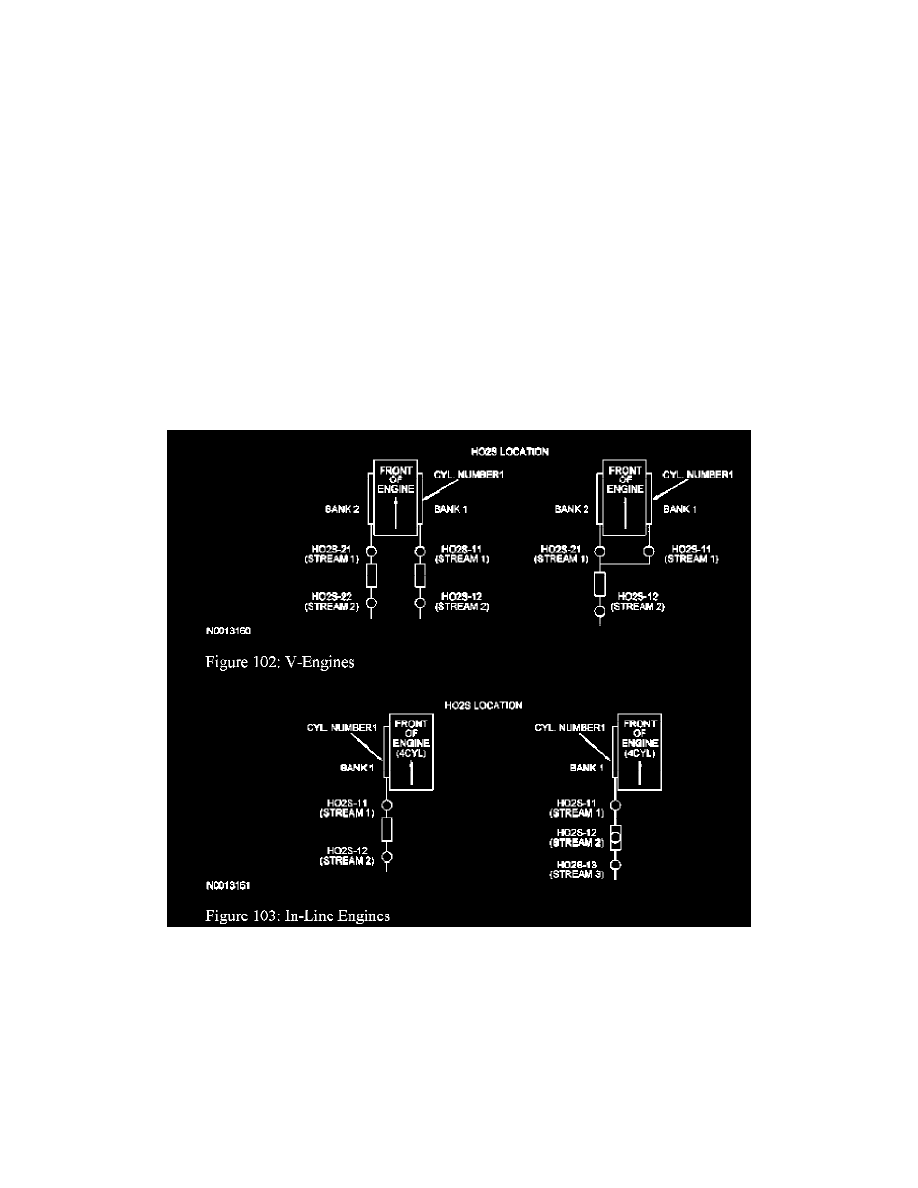
The number of HO2S used in the exhaust stream and the location of these sensors depend on the vehicle emission certification level (i.e. LEV ULEV
PZEV). On most vehicles only 2 HO2S are used in an exhaust stream. The front sensors (HO2S1 1/H02S21) before the catalyst will be used for
primary fuel control while the ones afier the catalyst (H02S12/H02S22) will be used to monitor catalyst efficiency. However some partial zero
emission vehicles (PZEV) will use 3 HO2S sensors for each engine bank. The stream 1 sensors (HO2S1 1/H02S21) located before the catalyst are
used for primary fuel control the stream 2 sensors (H02S12/H02S22) are used to monitor the light-off catalyst and the stream 3 sensors
(H02S13/H02S23) located afier the catalyst are used for long term fuel trim control to optimize catalyst efficiency (fore afi oxygen sensor control).
Current PZEV vehicles use only a 4-cylinder engine so only the Bank 1 HO2S will be used.
Catalytic Converter
A catalyst is a material that remains unchanged when it initiates and increases the speed of a chemical reaction. A catalyst will also enable a chemical
reaction to occur at a lower temperature. The concentration of exhaust gas products released to the atmosphere must be controlled. The catalytic
converter assists in this task. It contains a catalyst in the form of a specially treated ceramic honeycomb structure saturated with catalytically active
precious metals. As the exhaust gases come in contact with the catalyst they are changed into mostly harmless products. The catalyst initiates and
speeds up heat producing chemical reactions of the exhaust gas components so they are used up as much as possible.
Light Off Catalyst
As the catalyst heats up converter efficiency rises rapidly. The point at which conversion efficiency exceeds 50% is called catalyst light off. For most
catalysts this point occurs at 246°C to 301°C (475°F to 575°F). A fast light catalyst is a 3-way catalyst (TWC) that is located as close to the exhaust