
Flex FWD V6-3.5L (2010)
Valve Clearance: Adjustments
Valve Clearance Check
1. Remove the valve covers. For additional information, refer to Valve Cover - LH See: Engine, Cooling and Exhaust/Engine/Cylinder Head
Assembly/Valve Cover/Service and Repair/Valve Cover - LH and Valve Cover - RH See: Engine, Cooling and Exhaust/Engine/Cylinder Head
Assembly/Valve Cover/Service and Repair/Valve Cover - RH.
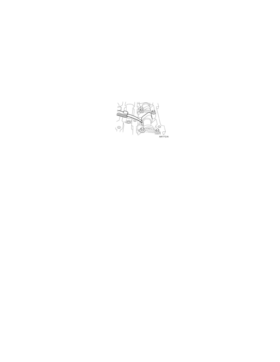
2. NOTE: Engine must be at room temperature before measuring. The valve clearance must be measured with the camshaft at base circle. The engine
will have to be rotated with the crankshaft pulley bolt to bring each valve to base circle.
Use a feeler gauge to measure the clearance of each valve and record its location. A midrange clearance is the most desirable:
-
Intake: 0.15-0.25 mm (0.006-0.01 in)
-
Exhaust: 0.360-0.460 mm (0.0142-0.0181 in)
3. NOTE: The number on the valve tappet reflects the thickness of the valve tappet. For example, a tappet with the number 3.310 has the thickness
of 3.31 mm (0.13 in).
If any of the valve clearances are out of specification, select new tappets using this formula: tappet thickness = measured clearance + the base
tappet thickness - most desirable thickness.
Select the tappets and mark the installation location.
4. If required, install the new selected valve tappets in the marked locations. For additional information, refer to Valve Tappets See: Engine, Cooling
and Exhaust/Engine/Camshaft, Lifters and Push Rods/Lifter / Lash Adjuster/Service and Repair/Removal and Replacement/Valve Tappets -
Removal.