
Flex FWD V6-3.5L (2010)
3. Connect the scan tool to the DLC.
-
NOTE: Make sure to use the latest scan tool software release.
NOTE: The Vehicle Communication Module (VCM) LED prove-out confirms power and ground from the DLC are provided to the VCM.
If the Integrated Diagnostic System (IDS) does not communicate with the VCM:
-
Check the VCM connection to the vehicle.
-
Check the scan tool connection to the VCM.
-
GO to Pinpoint Test Y, to diagnose No Power To The Scan Tool. See: Pinpoint Tests/Pinpoint Test Y: No Power To The Scan Tool
4. Establish a scan tool session.
-
NOTE: The scan tool first attempts to communicate with the PCM, after establishing communication with the PCM, the scan tool then
attempts to communicate with all other modules on the vehicle.
If an IDS session cannot be established with the vehicle, (IDS may state "No communication can be established with the PCM"):
-
Choose "NO" when the scan tool prompts whether or not to retry communication.
-
Enter either a PCM part number, tear tag or calibration number to identify the vehicle and start a session (the PCM part number and
4-character tear tag are printed on the PCM label).
-
GO to Pinpoint Test A, The PCM Does Not Respond To The Scan Tool. See: Pinpoint Tests/Pinpoint Test A: The PCM Does Not
Respond To The Scan Tool
5. Carry out the network test.
-
If the network test passes, retrieve and record the continuous memory DTCs and proceed to Step 6.
-
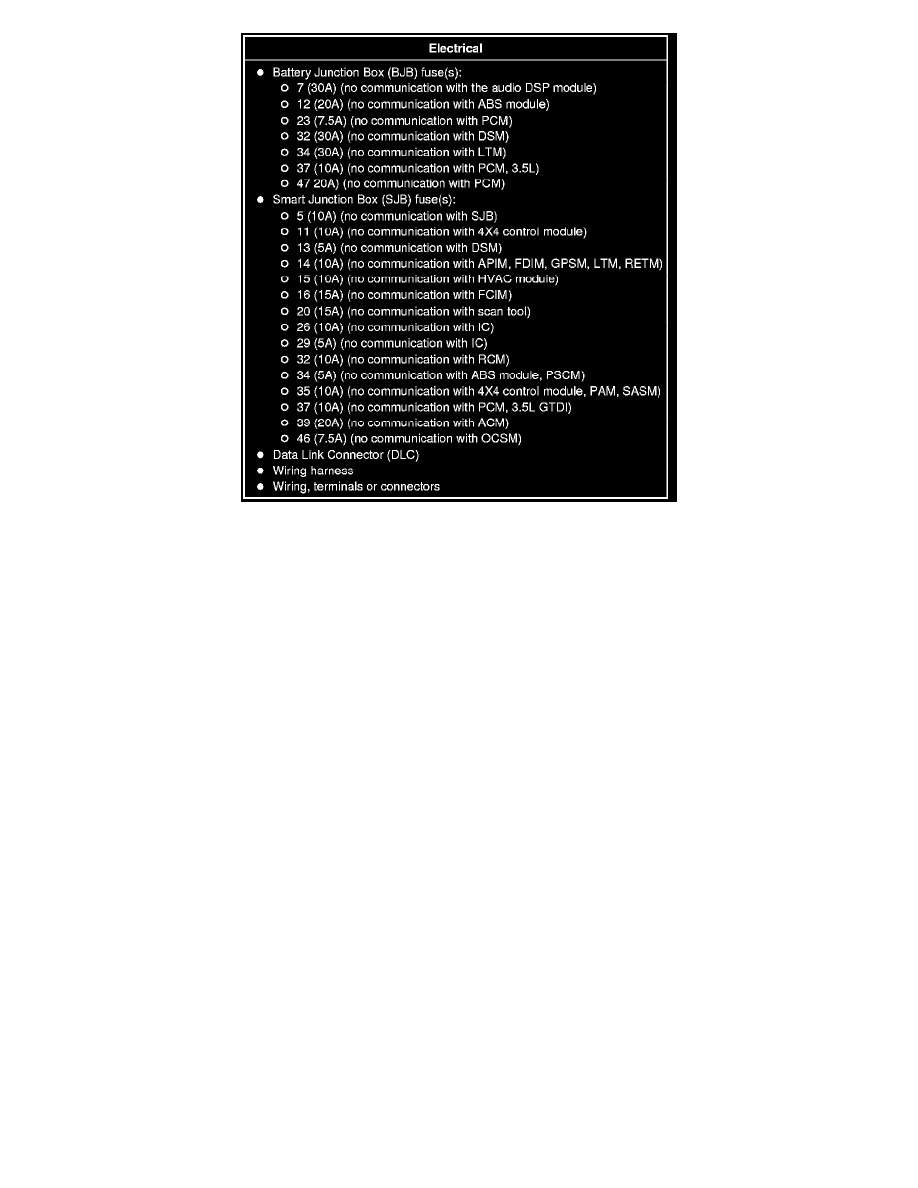
If the network test fails, GO to Symptom Chart to diagnose the failed communication network. See: Symptom Related Diagnostic Procedures
-
If a module fails to communicate during the network test, GO to Symptom Chart. See: Symptom Related Diagnostic Procedures
6. Retrieve and review the DTCs.
-
If the DTCs retrieved are related to the concern, go to DTC Charts. Follow the non-network DTC diagnostics (B-codes, C-codes, P-codes)
prior to the network DTC diagnostics (U-codes). For all other DTCs, refer to the Diagnostic Trouble Code (DTC) Chart in Body Control
Systems. See: Diagnostic Trouble Code Descriptions/Module Communications Network See: Body and Frame/Body Control Systems/Testing