
Flex FWD V6-3.5L (2010)
Refer to Wiring Diagram Set 130, Audio System/Navigation for schematic and connector information. See: Diagrams/Electrical Diagrams/Diagrams By
Number
Normal Operation
The Global Positioning System Module (GPSM) communicates with the scan tool through the Medium Speed Controller Area Network (MS-CAN).
This pinpoint test is intended to diagnose the following:
-
Fuse
-
Wiring, terminals or connectors
-
GPSM
PINPOINT TEST S: THE GPSM DOES NOT RESPOND TO THE SCAN TOOL
NOTICE: Use the correct probe adapter(s) when making measurements. Failure to use the correct probe adapter(s) may damage the
connector.
NOTE: Failure to disconnect the battery when instructed will result in false resistance readings. Refer to Battery.
-------------------------------------------------
S1 CHECK THE GPSM VOLTAGE SUPPLY CIRCUIT FOR AN OPEN
-
Ignition OFF.
-
Disconnect: GPSM C2300.
-
Ignition ON.
-
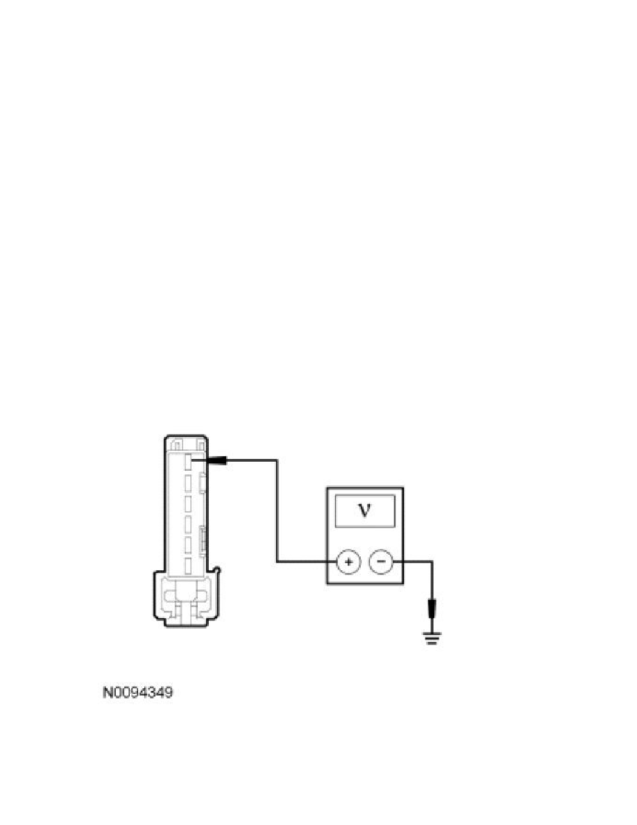
Measure the voltage between the GPSM C2300-1, circuit SBP14 (BN/RD), harness side and ground.
-
Is the voltage greater than 10 volts?
Yes
GO to S2.