
Flex FWD V6-3.5L (2010)
CONNECT the negative battery cable. GO to V39.
No
REPAIR the circuit in question. CONNECT the negative battery cable. CLEAR the DTCs. REPEAT the network test with the scan tool.
-------------------------------------------------
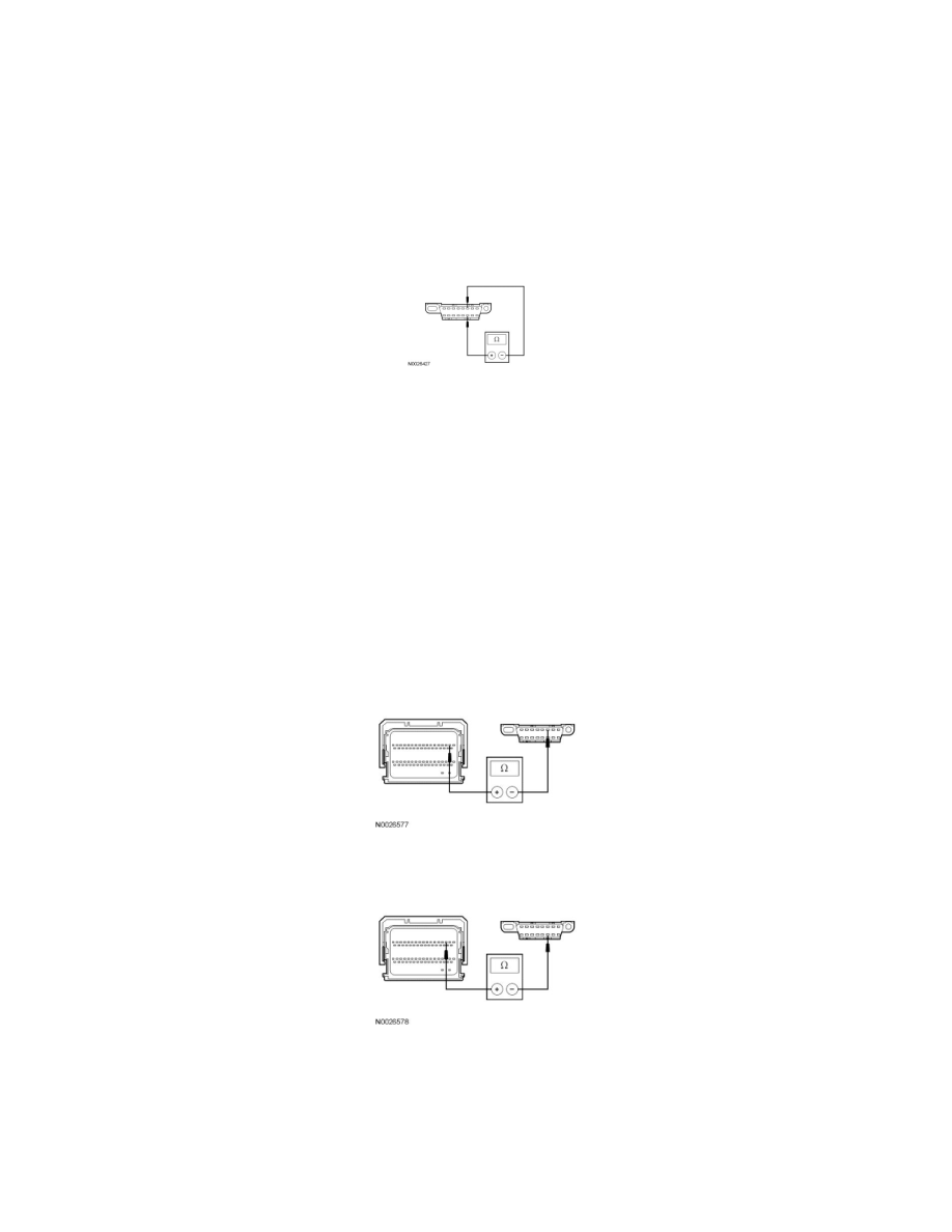
V9 CHECK THE HS-CAN (+) AND HS-CAN (-) CIRCUITS FOR A SHORT TOGETHER
-
Measure the resistance between the DLC C251-6, circuit VDB04 (WH/BU), harness side and the DLC C251-14, circuit VDB05 (WH), harness
side.
-
Is the resistance less than 5 ohms?
Yes
GO to V11.
No
GO to V10.
-------------------------------------------------
V10 CHECK THE HS-CAN CIRCUITS BETWEEN THE PCM AND THE DLC FOR AN OPEN
-
For 3.5L, measure the resistance between the PCM C175b-2, circuit VDB04 (WH/BU), harness side and the DLC C251-6, circuit VDB04
(WH/BU), harness side.
-
For 3.5L, measure the resistance between the PCM C175b-3, circuit VDB05 (WH), harness side and the DLC C251-14, circuit VDB05 (WH),
harness side.
-
For 3.5L GTDI, measure the resistance between the PCM C1381b-59, circuit VDB04 (WH/BU), harness side and the DLC C251-6, circuit
VDB04 (WH/BU), harness side.