
Flex FWD V6-3.5L (2010)
-
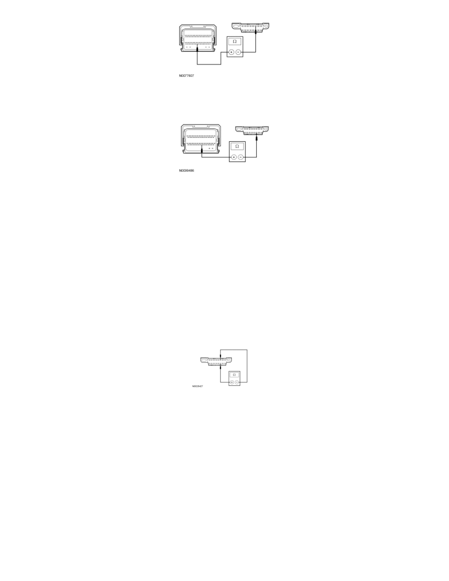
For 3.5L GTDI, measure the resistance between the PCM C1381b-58, circuit VDB05 (WH), harness side and the DLC C251-14, circuit VDB05
(WH), harness side.
-
Are the resistances less than 5 ohms?
Yes
The CAN has tested within specifications. CONNECT the negative battery cable. VERIFY the scan tool operation on a substitute vehicle, and REPEAT
the network test on the suspect vehicle.
No
A capacitor internal to a module may still be draining causing irregular resistance readings. WAIT 5 minutes. REPEAT the pinpoint test.
-------------------------------------------------
V11 CHECK THE HS-CAN (+) AND HS-CAN (-) CIRCUITS FOR A SHORT TOGETHER WITH THE PCM DISCONNECTED
-
Disconnect: PCM C175b or C1381b.
-
Measure the resistance between the DLC C251-6, circuit VDB04 (WH/BU), harness side and the DLC C251-14, circuit VDB05 (WH), harness
side.
-
Is the resistance less than 5 ohms?
Yes
If the vehicle is equipped with a Parking Aid Module (PAM), GO to V12.
If the vehicle is not equipped with a PAM, GO to V13.
No
CONNECT the negative battery cable. GO to V31.
-------------------------------------------------
V12 CHECK THE HS-CAN (+) AND HS-CAN (-) CIRCUITS FOR A SHORT TOGETHER WITH THE PAM DISCONNECTED
-
Disconnect: PAM C3267.
-
Measure the resistance between the DLC C251-6, circuit VDB04 (WH/BU), harness side and the DLC C251-14, circuit VDB05 (WH), harness
side.