
Focus L4-2.0L (2009)
6. Remove the oil level indicator and tube. For additional information, refer to Oil Level Indicator and Tube See: Engine Lubrication/Engine Oil Dip
Stick - Dip Stick Tube/Service and Repair/Oil Level Indicator and Tube.
7. Disconnect the Engine Oil Pressure (EOP) switch electrical connector and detach the wire harness retainer from the starter stud bolt.
8. Disconnect the electronic throttle control electrical connector.
9. Disconnect the fuel vapor return hose.
10. Disconnect the power brake booster vacuum tube.
-
Depress the quick release locking ring.
-
Pull the vacuum tube out of the quick release fitting.
11. Disconnect the Manifold Absolute Pressure (MAP) sensor electrical connector.
12. Detach and disconnect the Knock Sensor (KS) electrical connector.
13. If equipped, disconnect the swirl control valve solenoid electrical connector.
14. If equipped, disconnect the swirl control valve sensor electrical connector.
15. Detach all the wiring harness pin-type retainers from the intake manifold.
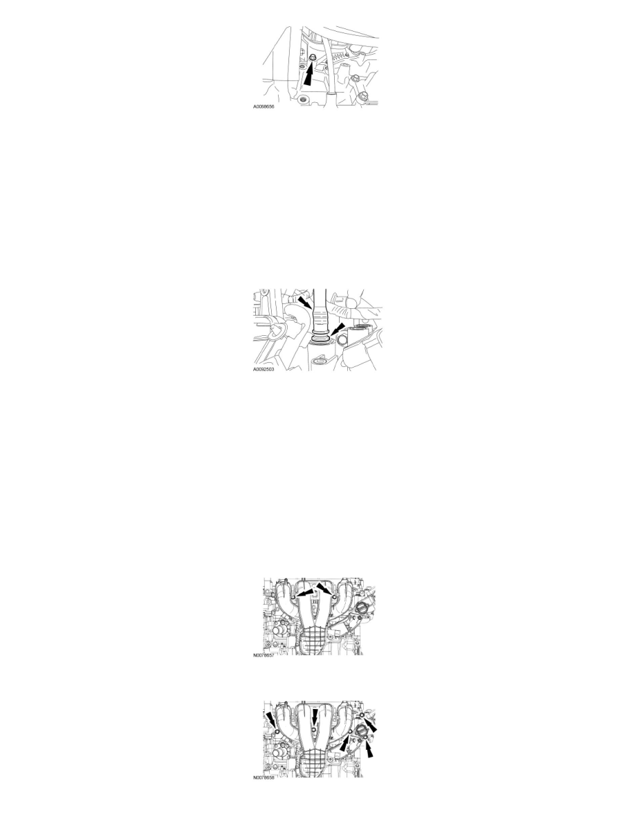
16. NOTE: The 2 intake manifold bolts differ in length from rest of the bolts and also retain a crash bracket to the intake manifold. The 2 bolts are
equipped with an attachment feature that allows them to be loosened but remain attached to the intake manifold. Do not attempt to remove the 2
bolts or the crash bracket from the intake manifold.
Loosen the 2 intake manifold bolts.
17. Remove the 5 intake manifold bolts.