
Focus L4-2.0L (2009)
-
Are the voltages greater than 10 volts?
Yes
GO to B2.
No
VERIFY the Battery Junction Box (BJB) fuses 18 (20A), 9 (40A) and the Smart Junction Box (SJB) fuse 31 (10A) are OK. If OK, REPAIR the circuit
in question. If not OK, REFER to the Wiring Diagrams to identify the possible causes of the circuit short. CLEAR the DTCs. REPEAT the network test
with the scan tool.
-------------------------------------------------
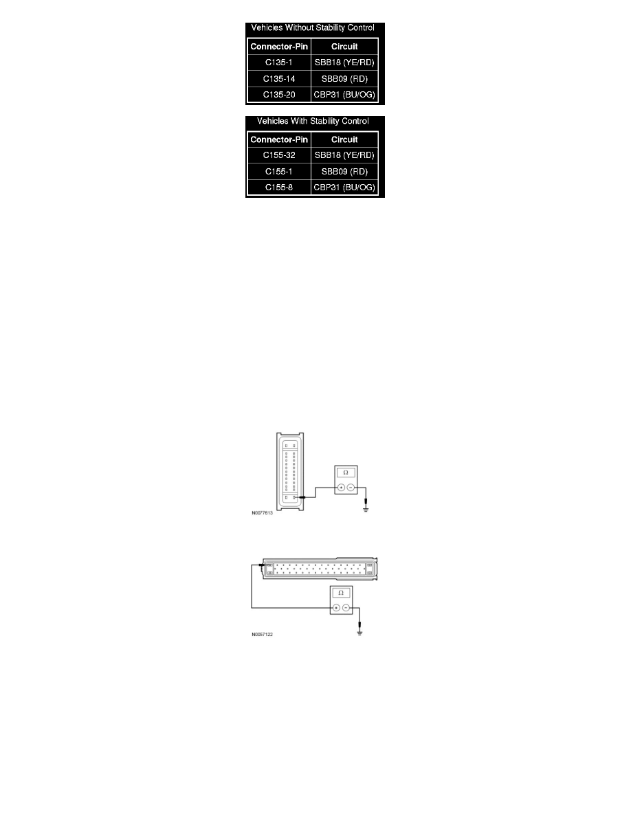
B2 CHECK THE ABS MODULE GROUND CIRCUIT FOR AN OPEN
-
Ignition OFF.
-
Disconnect: Negative Battery Cable.
-
For vehicles without stability control, measure the resistance between the ABS module C135-26, circuit GD122 (BK), harness side and ground.
-
For vehicles with stability control, measure the resistance between the ABS module C155-16, circuit GD122 (BK), harness side and ground.
-
Is the resistance less than 5 ohms?
Yes
GO to B3.
No
REPAIR the circuit. CONNECT the negative battery cable. CLEAR the DTCs. REPEAT the network test with the scan tool.
-------------------------------------------------
B3 CHECK THE HS-CAN CIRCUITS BETWEEN THE ABS MODULE AND THE DLC FOR AN OPEN