
Focus L4-2.0L (2009)
-------------------------------------------------
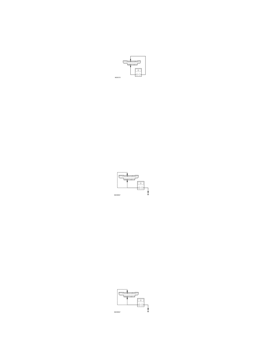
M17 CHECK THE MS-CAN (+) AND MS-CAN (-) CIRCUITS FOR A SHORT TOGETHER
WITH THE IC DISCONNECTED
-
Disconnect: IC C220.
-
Measure the resistance between the DLC C251-3, circuit VDB06 (GY/OG), harness side and the DLC C251-11, circuit VDB07 (VT/OG), harness
side.
-
Is the resistance less than 5 ohms?
Yes
REPAIR the circuit. CONNECT all modules. CONNECT the negative battery cable. CLEAR the DTCs. REPEAT the network test with the scan tool.
No
CONNECT the negative battery cable. GO to M31.
-------------------------------------------------
M18 CHECK THE MS-CAN (+) AND MS-CAN (-) CIRCUITS FOR A SHORT TO
GROUND WITH THE SJB DISCONNECTED
-
Disconnect: SJB C2280b.
-
Measure the resistance between the DLC C251-3, circuit VDB06 (GY/OG), harness side and ground; and between the DLC C251-11, circuit
VDB07 (VT/OG), harness side and ground.
-
Are the resistances greater than 1,000 ohms?
Yes
CONNECT the negative battery cable. GO to M25.
No
GO to M19.
-------------------------------------------------
M19 CHECK THE MS-CAN (+) AND MS-CAN (-) CIRCUITS FOR A SHORT TO
GROUND WITH THE HVAC MODULE DISCONNECTED
-
Disconnect: HVAC Module C2357a.
-
Measure the resistance between the DLC C251-3, circuit VDB06 (GY/OG), harness side and ground; and between the DLC C251-11, circuit
VDB07 (VT/OG), harness side and ground.
-
Are the resistances greater than 1,000 ohms?
Yes