
Focus L4-2.0L DOHC VIN 3 (2002)
7. CAUTION: When installing the switches, the stop lamp switch is rotated to the counterclockwise and the remaining switches are rotated to the
clockwise. Failure to follow this instruction will result in the switch plungers binding inside the switch.
CAUTION: Make sure the switches are correctly installed.
NOTE: The speed control deactivation switch and the stop lamp switch are automatically adjusted during installation.
NOTE: A slight ratcheting noise and feel during installation of the speed control deactivation switch and the stop lamp switch is normal.
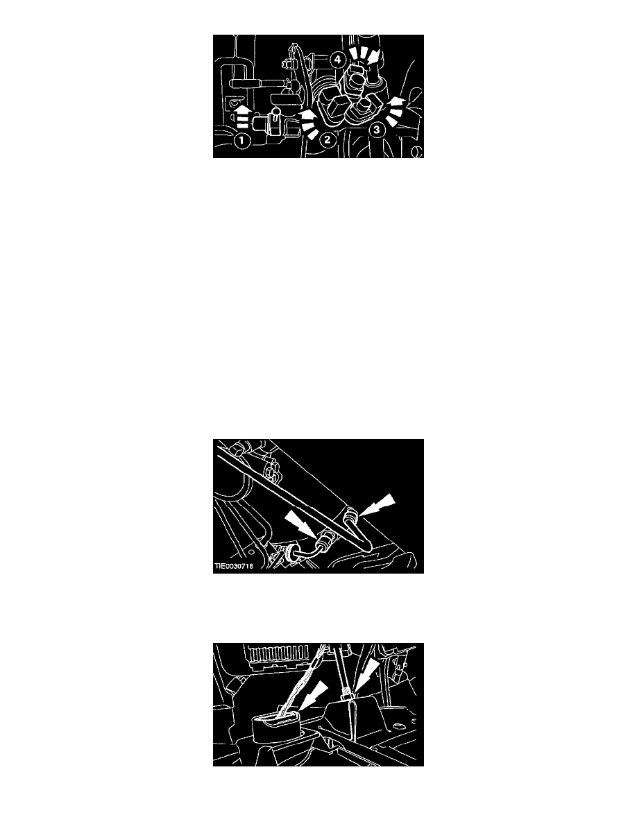
Install the switches to the pedal assembly.
1. Speed control deactivation switch (colored green).
2. Stop lamp switch (colored gray).
3. Clutch position switch (colored red).
4. Starter safety switch (colored black).
8. NOTE: The colors of the electrical connectors and the switches are identical.
Connect the electrical connectors to the pedal assembly switches.
9. NOTE: A slight ratcheting noise and feel during switch adjustment is normal.
Adjust the starter safety switch (colored black) by pressing and then releasing the clutch pedal.
10. NOTE: Install new O-ring seals if necessary.
Connect the clutch master cylinder and slave cylinder fluid supply lines to the clutch master cylinder.
-
Insert the clips.
11. Connect the hood release cable and the data link connector (DLC) to the instrument panel lower panel.