
Focus L4-2.0L SOHC VIN P (2000)
Component Identification Information
Component Identification Information consists of
(1) A-Z Component List,
(2) Component Location Views, and
(3) Connector views (Faces).
The A-Z Component List helps the user find where the various items depicted on the diagram can physically be found on the vehicle. A brief written
description of the location is given.
The Component Location Views show the components and their connecting wires as they can be found on the vehicle.
The Connector Views show the views of the pins and/or cavities of all connectors. The pin and cavity sides are shown separately as if the connector
were disconnected. The color of the connector housing is indicated next to the connector number.
Vacuum Motor Operation
Vacuum motors operate like electrical solenoids, mechanically pushing or pulling a shaft between two fixed positions. When vacuum is not applied, the
shaft is pushed all the way out by a spring.
Some vacuum motors can position the actuating arm at any position between fully extended and fully retracted. The Servo is operated by a control valve
that applies varying amounts of vacuum to the motor. The higher the vacuum level, the greater the retraction of the motor arm. Servo Motors work nearly
the same way as two-position motors, except for the way the vacuum is applied. Servo Motors are generally larger and provide a calibrated control.
A double diaphragm motor has three positions (it is actually two motors in one housing). When the top port gets vacuum, the shaft pulls halfway in.
When both ports get vacuum, the shaft pulls all the way in.
WARNINGS
^
Always wear safety glasses for eye protection.
^
Use safety stands whenever a procedure requires being under a vehicle.
^
Be sure that the Ignition Switch is always in the OFF position, unless otherwise required by the procedure.
^
Set the parking brake when working on any vehicle. An automatic transmission should be in PARK. A manual transmission should be in
NEUTRAL.
^
Operate the engine only in a well-ventilated area to avoid danger of carbon monoxide.
^
Keep away from moving parts, especially the fan and belts, when the engine is running.
^
To prevent serious burns, avoid contact with hot metal parts such as the radiator, exhaust manifold, tall pipe, catalytic converter and muffler.
^
Do not allow flame or sparks near the battery. Gases are always present in and around the battery. An explosion could occur.
^
Do not smoke when working on a vehicle.
^
To avoid injury always remove rings, watches, loose hanging jewelry and avoid wearing loose clothing.
circuit Numbering
Circuit Numbering and Wire Identification
Circuit Numbering:
Ford has introduced a world-wide uniform system for circuit numbering and wire identification.
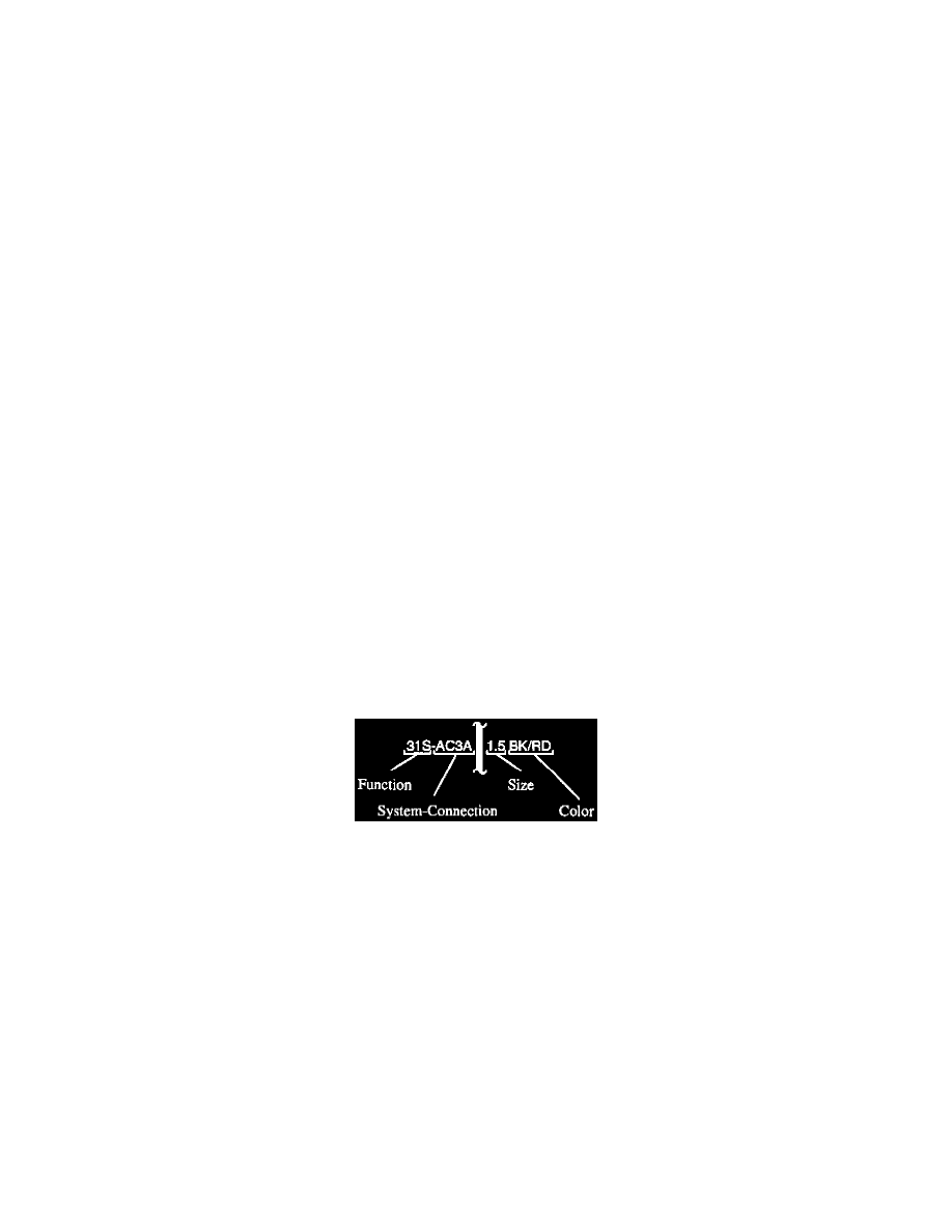
The system is called Function, System-Connection, or FSC for short.
FSC was developed mainly to assist in vehicle development and production processes, but is also helpful in troubleshooting electrical circuits.
Function:
The first two digits identify the function of the wire. In this case, the function code includes the letter "S" to indicate it is an additionally
switched function. The function part of the circuit number is the most helpful to the technician in troubleshooting a circuit.
System-Connection (including branch):
Systems are related to subsets of the vehicle circuitry. Immediately following the system letter code is the connection number specific to
that system. A branch identification is used to differentiate wires in one connection with the same function.
Wire Identification (wire colors):
The wire identification consists of a basic color and an identification color, and is determined directly from the wire's circuit number. In the
schematics the wire colors are indicated next to the wires.
The basic and identification colors are abbreviated using the international norm IEC 757.
Each function code has a specific basic color associated with it. A colored stripe is used to differentiate several wires with the same function
within one component connector.