| Removal and Installation Special Tool(s) | | Lever, Wheel Knuckle 204-159 (14-039) | | | Installer, Halfshaft 204-161 (14-041) | | | Separator, Ball Joint 211-020 (13-006) | General Equipment Removal All vehicles | | -
CAUTION:Use a socket to loosen the wheel hub retaining nut to prevent damage. Loosen the wheel hub retaining nut. | | | -
Loosen the strut and spring assembly top mount nuts by five turns. | | | -
Detach the brake hose from the suspension unit. | Vehicles with anti-lock brakes | | -
Detach the front wheel speed sensor from the wheel knuckle. | All vehicles | | -
Remove the front brake caliper retaining bolts. - Remove the bolt covers.
- Remove the bolts.
| | | -
CAUTION:Suspend the brake caliper to prevent load being placed on the brake hose. Detach the front brake caliper from the wheel knuckle. - Rotate the retaining spring.
- Detach and suspend the front brake caliper assembly.
| | | -
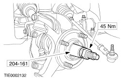
CAUTION:Leave the tie-rod end retaining nut in place to protect the ball joint stud. Loosen the tie-rod end retaining nut. | | | -
CAUTION:Protect the ball joint seal using a soft cloth to prevent damage. Using the special tool, detach the tie-rod end from the wheel knuckle. - Discard the tie-rod end retaining nut.
| | | -
CAUTION:Protect the ball joint seal using a soft cloth to prevent damage. Detach the lower arm ball joint from the wheel knuckle. - Remove the pinch bolt.
- Detach the lower arm ball joint from the wheel knuckle.
| | | -
CAUTION:Use a socket to remove the wheel hub retaining nut to prevent damage. Remove the wheel hub retaining nut. | | | -
CAUTION:Support the halfshaft. The inner joint must not be bent more than 18 degrees. The outer joint must not be bent more than 45 degrees. Using a suitable three leg puller puller, detach the halfshaft from the wheel hub. | | | -
Remove the wheel knuckle to suspension unit pinch bolt. | | | -
Using the special tool, remove the wheel knuckle. - Insert the special tool and rotate through 90 degrees.
- Remove the wheel knuckle.
- Secure the halfshaft out of the way.
| Installation All Vehicles | | -
Install the wheel knuckle. | | | -
CAUTION:Make sure the halfshaft is completely installed into the wheel hub. Using the special tool, install the halfshaft into the wheel hub. | | | -
CAUTION:Make sure the heat shield is installed to prevent damage to the ball joint. Attach the lower arm ball joint to the wheel knuckle. | Vehicles with anti-lock brakes | | -
Attach the front wheel speed sensor to the wheel knuckle. | All vehicles | | -
Attach the brake caliper to the wheel knuckle. - Install the bolts.
- Install the bolt covers.
| | | -
WARNING:Install a new tie-rod end retaining nut. Failure to follow this instruction may result in personal injury. Attach the tie-rod end to the wheel knuckle. | | | -
Attach the brake hose to the suspension unit. | | | -
CAUTION:The wheel hub retaining nut can be re-used four times, mark the wheel hub retaining nut. CAUTION:Use a socket to tighten the wheel hub retaining nut to prevent damage. With the aid of another technician, apply the brakes and pre load the wheel bearing by installing the wheel hub retaining nut. | | | -
CAUTION:Use a socket to tighten the wheel hub retaining nut to prevent damage. Tighten the wheel hub retaining nut. | | | -
Tighten the strut and spring assembly top mount retaining nuts. | |