| Removal and Installation Special Tool(s) | | Expander, Teflon Seal 211-188 (13-015) | | | Expander, Teflon Seal 211-243 (13-023) | | | Socket, Union Nut, Hydraulic Pipe 211-244 (13-024) | | | Remover, Oil Cooling Pipe 307-242 (17-049) | Removal All Vehicles NOTE:Whenever the hoses are disconnected from the power steering pump, make sure the accessory drive belt is not contaminated with power steering fluid. | | -
Disconnect the battery ground cable. | Vehicles with diesel engine | | -
Remove the engine undershield. | All Vehicles | | -
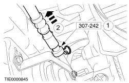
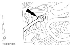
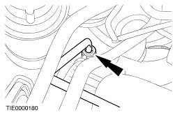
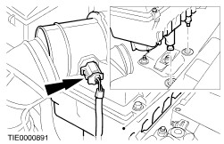
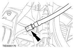
Using the special tool, disconnect the fluid cooler hose. - Insert the special tool into the hose quick- release coupling.
- Move the special tool along the hose to release the locking tangs.
- Allow the fluid to drain into a suitable container.
| | | -
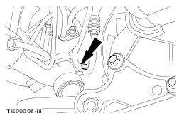
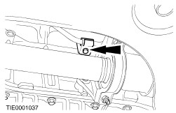
NOTE:Left-hand drive shown, right-hand drive similar. Detach the hose support clamp. | | | -
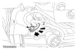
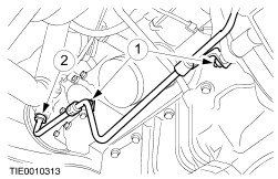
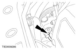
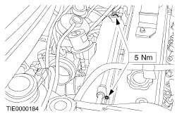
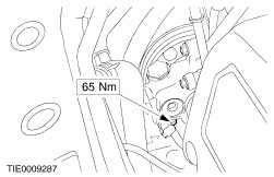
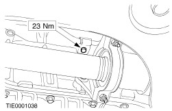
NOTE:Right-hand drive shown, left-hand drive similar. Detach the power steering hoses from the steering gear. - Remove the bolt.
- Rotate the clamp plate.
- Allow the fluid to drain into a suitable container.
| Vehicles with 1.4L or 1.6L engine without air conditioning | | -
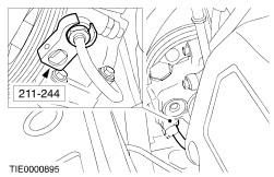
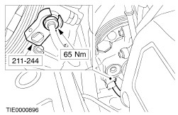
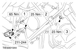
NOTE:Aluminium power steering pump. Using the special tool, disconnect the high-pressure hose union. - Detach the hose support brackets.
- Using the special tool, disconnect the hose union.
| | | -
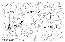
NOTE:Cast iron power steering pump. Disconnect the high-pressure hose union. - Detach the hose support brackets.
- Disconnect the hose union.
| Vehicles with 1.4L or 1.6L engine with air conditioning | | -
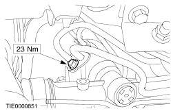
Detach the high-pressure hose support bracket. | | | -
Disconnect the high-pressure hose union. - Allow the fluid to drain into a suitable container.
| All Vehicles Vehicles with 1.8L or 2.0L engine | | -
Detach the high-pressure hose support brackets. - Detach the speed control cable (if equipped).
| | | -
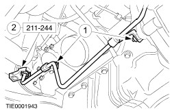
NOTE:Aluminium power steering pump. Using the special tool, disconnect the high-pressure hose union. - Allow the fluid to drain into a suitable container.
| | | -
NOTE:Cast iron power steering pump. Disconnect the high-pressure hose union. - Allow the fluid to drain into a suitable container.
| Vehicles with diesel engine | | -
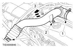
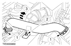
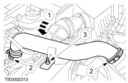
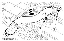
Remove the charge air cooler (CAC) to intake manifold ducting. - Loosen the clips.
- Remove the nut.
- Remove the ducting.
| | | -
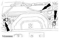
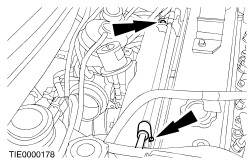
Detach the high-pressure hose support brackets. | | | -
Disconnect the high-pressure hose union. | | | -
Remove the CAC to turbocharger ducting. - Loosen the clips.
- Remove the nut.
- Remove the ducting.
| | | -
Disconnect the air cleaner to turbocharger outlet tube. | | | -
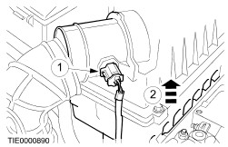
Detach the air cleaner. - Disconnect the air temperature sensor electrical connector.
- Lift out the air cleaner.
| All except diesel engine All Vehicles | | -
Remove the high-pressure hose. | Installation All Vehicles | | -
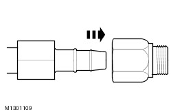
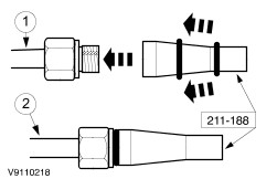
If a new hose is to be installed, push the new hose into the new union. | | | -
NOTE:Cast iron power steering pump. Using the special tool, install a new Teflon ® seal. - Push the seal onto the special tool.
- Locate the tool over the union and push on the seal.
| | | -
NOTE:Aluminium power steering pump. NOTE:Check the rubber O-ring seal for damage, install a new O-ring seal as necessary. Using the special tool, install a new Teflon ® seal. - Push the seal onto the special tool.
- Locate the tool over the union and push on the seal.
| | | -
CAUTION:Make sure the hose is routed correctly. Install the high-pressure hose into position. | Vehicles with diesel engine | | -
CAUTION:Make sure the hose is routed correctly. Install the high-pressure hose into position. | | | -
Install the air cleaner. - Connect the electrical connector.
| | | -
Connect the air cleaner to turbocharger outlet tube. | | | -
Install the CAC to turbocharger air ducting - Position the ducting.
- Tighten the clips.
- Install the nut.
| | | -
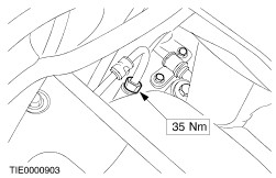
Connect the high-pressure hose union. | | | -
Install the high-pressure hose support brackets. | | | -
Install the CAC to intake manifold ducting. - Position the ducting.
- Tighten the clips.
- Install the nut.
| Vehicles with 1.8L or 2.0L engine | | -
NOTE:Aluminium power steering pump. Using the special tool, connect the high-pressure hose union. | | | -
NOTE:Cast iron power steering pump. Connect the high-pressure hose union. | | | -
Install the high-pressure hose support brackets. - Attach the speed control cable (if equipped).
| Vehicles with 1.4L or 1.6L engine with air conditioning | | -
Connect the high-pressure hose union. | All Vehicles Vehicles with 1.4L or 1.6L engine with air conditioning | | -
Install the high-pressure hose support bracket. | Vehicles with 1.4L or 1.6L engine without air conditioning | | -
NOTE:Aluminium power steering pump. Using the special tool, connect the high-pressure hose union. - Connect the hose union.
- Install the hose left-hand support bracket.
- Install the hose right-hand support bracket.
| | | -
NOTE:Cast iron power steering pump. Connect the high-pressure hose union. - Connect the hose union.
- Install the hose left-hand support bracket.
- Install the hose right-hand support bracket.
| All Vehicles | | -
Install the power steering hoses. - Install the hoses and rotate the clamp plate.
| | | -
Install the hose support clamp. | | | -
Connect the fluid cooler hose. | Vehicles with diesel engine | | -
Install the engine undershield. | All Vehicles | | -
Connect the battery ground cable. | |