| Assembly Special Tool(s) | | Universal Flange Holding Wrench 205-072 (15-030A) | | | Gauge, Bolt Angle 303-174 (21-540) | | | Timing Peg, Crankshaft TDC 303-193 (21-104) | | | Installer, Camshaft Seal 303-199A (21-110A) | | | Alignment Plate, Camshaft 303-376 (21-162B) | | | Locking Tool, Flywheel 303-393 (21-168) | | | Remover/Installer, Hose Clamp 303-397 (24-003) | | | Mounting Stand 303-435 (21-187) | | | Mounting Bracket for 303-435 303-435-06 (21-031B) | | | Aligner, Oil Pump 303-652 (21-230) | | | Timing Tool, Crankshaft 303-710 (21-257) | | | Aligner, Clutch Disc 308-204 (16-067) | General Equipment Micrometer Feeler gauges Internal micrometer Piston ring compressor Dial indicator gauge holding fixture Dial indicator gauge Plastigage Engine vacuum cleaner Materials Name Specification Silicone gasket and sealant WSE-M4G323-A4 Sealer WSK-M2G348-A5 Engine oil SAE 5W 30 WSS-M2C912-A1 Assembly CAUTION:Diesel fuel injection equipment is manufactured to very precise tolerances and fine clearances. It is therefore essential that absolute cleanliness is observed when working with these components. Always fit blanking plugs to any open orifices or lines. CAUTION:Do not disassemble or clean inside the fuel injection supply manifold, even with an ultrasonic cleaner. CAUTION:Always carry out the cleaning process before carrying out any repairs to fuel system components to prevent foreign material entering the components. | | -
Coat the main bearing journals, bearing shells and thrust half washers with clean engine oil. | | | -
Install the main bearing shells to the cylinder block and to the main bearing caps. | | | -
Position the crankshaft in the cylinder block. | | | -
NOTE:The grooves in the thrust half washers must face outwards. Install the crankshaft thrust half washers into the third main bearing with oil grooves facing outwards. | | | -
NOTE:Install the main bearing caps with arrows pointing forward. Caps are identified 1, 2, 3, 4, 5 from the front to the rear. Install the crankshaft. - Tighten the bolts in three stages in the sequence shown.
- Stage 1: Tighten the bolts 1 through 10 to 45 Nm.
- Stage 2: Tighten the bolts 1 through 10 to 70 Nm.
- Stage 3: Tighten the bolts 1 through 10 to 60 degrees.
| | | -
NOTE:Install the pistons with the arrows pointing to the front of the engine. NOTE:The piston ring gaps and oil supply ring elements must be distributed evenly around the circumference. Using a suitable piston ring compressor, install the pistons. - Install clean and dry connecting rod bearing shells in the connecting rods.
| | | -
CAUTION:Connecting rod bearing cap bolts must only be used two times. NOTE:Stamp the bolt heads with a center punch to indicate usage. NOTE:The big-end bearing caps identification marks must point to the front of the engine. Using the special tool, install the connecting rod bearing caps. - Tighten the bolts in four stages.
- Stage 1: Tighten the bolts finger tight.
- After installation lubricate the journals with engine oil.
| | | -
NOTE:Install a new timing chain rear housing gasket. Install the timing chain rear housing. | | | -
NOTE:Install a new ladder frame gasket. Install the ladder frame (14 bolts). - Align the ladder frame flush with the cylinder block.
- Tighten the bolts in the sequence shown.
| | | -
Install the air conditioning (A/C) compressor retaining bracket. | | | -
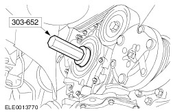
NOTE:Install a new oil pump pickup tube O-ring seal. Install the oil pump pickup tube. | | | -
NOTE:Install new O-ring seals. Install the oil pump connecting pipe. | | | -
NOTE:A new crankshaft rear oil seal carrier is supplied with an alignment sleeve that must be removed following installation. NOTE:Do not fully tighten the crankshaft rear oil seal carrier retaining bolts at this stage. Install the crankshaft rear oil seal carrier. | | | -
Tighten the crankshaft rear oil seal carrier retaining bolts. | | | -
Remove the crankshaft rear oil seal carrier alignment sleeve. | | | -
Using the special tool, install the crankshaft position (CKP) sensor retaining bracket. | | | -
CAUTION:Make sure that the sealer does not enter the ladder frame blind holes. Failure to follow this instruction may result in damage to the engine assembly. NOTE:Do not damage the mating faces. NOTE:The mating faces and blind holes must be free of oil and sealer residue. Clean the mating faces of the oil pan and ladder frame. | | | -
NOTE:Install the oil pan within ten minutes of applying the sealer. NOTE:Once the oil pan has contact with the ladder frame it must not be removed. Install the oil pan. - Tighten bolts and nuts in the sequence shown.
| | | -
NOTE:Inspect the oil pan drain plug seal for damage. Install a new drain plug and seal if required. Install the drain plug. | | | -
NOTE:Install new flywheel bolts. NOTE:Do not fully tighten the flywheel bolts at this stage. Install the dual mass flywheel. | | | -
Using the special tool, lock the dual mass flywheel in position. | | | -
NOTE:Install new flywheel bolts. NOTE:Do not fully tighten the flywheel bolts at this stage. Using the special tool, install the dual mass flywheel. - Tighten the bolts in two stages in the sequence shown.
| | | -
Inspect the dual mass flywheel.
For additional information, refer to: Flywheel Inspection - Vehicles With: Dual Mass Flywheel (303-00 Engine System - General Information, General Procedures).
| | | -
Using the special tool, centralize the clutch disc on the pressure plate. | | | -
CAUTION:Tighten the clutch pressure plate retaining bolts finger tight and then by two turns at a time in the sequence shown to the specified torque. Using the special tool, install the clutch disc and pressure plate. | | | -
NOTE:Install a new crankshaft position (CKP) sensor. NOTE:The CKP sensor must make contact with the flywheel. Install the CKP sensor. | | | -
Install the fuel pump bracket. | | | -
Install the coolant distribution pipe. | | | -
Using the special tool, attach the upper coolant hose to the coolant distribution pipe. | | | -
NOTE:Install a new fuel pump gasket. Install the fuel pump. | | | -
Install the fuel pump bracket. | | | -
Install the timing chain, sprockets and guides. | | | -
Install the fuel pump sprocket. | | | -
Install the timing chain tensioner. | | | -
NOTE:Install a new timing chain housing cover gasket. Using the special tool, install the timing chain housing cover. - Tighten the bolts in the sequence shown in three stages.
| | | -
Install the accessory drive belt idler. | | | -
NOTE:Install a new crankshaft front seal. Using the special tool, install the crankshaft front seal. | | | -
NOTE:Install a new crankshaft pulley bolt. Using the special tool, install the crankshaft pulley. - Tighten the bolt in two stages.
| | | -
NOTE:Install a new water pump gasket. Install the water pump. | | | -
Using the special tool, install the water pump pulley. | | | -
Install the engine front mount bracket. | | | -
CAUTION:The thickness of the new cylinder head gasket must be the same as that of the old one (hole/tooth marked). NOTE:Install a new cylinder head gasket. Install the cylinder head gasket. | | | -
CAUTION:Install new cylinder head bolts. Install the cylinder head bolts. - Using the special tool, tighten the bolts in four stages in the sequence shown.
- Stage 1: Tighten the bolts 1 through 10 to 20 Nm.
- Stage 2: Tighten the bolts 1 through 10 to 54 Nm.
- Stage 3: Tighten the bolts 1 through 10 to 90 degrees.
- Stage 4: short bolts: 70 degrees, long bolts: 90 degrees.
| | | -
Install the timing belt rear cover. | | | -
NOTE:Install a new fuel pump oil seal retainer. Install the fuel pump oil seal retainer. | | | -
Using sealant, seal the injection pump pulley to the fuel pump sprocket. - Apply sealant to the outer edge of the fuel pump pulley bolt holes.
| | | -
Install the fuel pump pulley. | | | -
Using the special tool, install the camshaft oil seal. | | | -
NOTE:Do not fully tighten the camshaft pulley retaining bolt at this stage. Install the camshaft pulley retaining bolt. | | | -
Install the special tool. | | | -
Install the special tool. - Remove the cylinder block blanking plug.
| | | -
NOTE:Only turn the crankshaft in the normal direction of rotation. Turn the crankshaft to top dead center (TDC). - Turn the crankshaft slowly until the crankshaft stops.
| | | -
CAUTION:Make sure that the engine does not rotate during installation of the special tool. CAUTION:Make sure engine is at the TDC position before locking the special tool. CAUTION:Make sure that the special tool engages correctly. Using the special tool, lock the engine in position. | | | -
NOTE:Use only latest level timing belts. These are identified by a laser etched Ford logo. Check the timing belt. | | | -
Check the timing belt tensioner. - Make sure that the tensioner pointer rotates clockwise freely.
- Arrow denotes counterclockwise rotation of tensioner.
| | | -
Rotate the timing belt tensioner adjustment arm clockwise to the 3 o'clock position. | | | -
NOTE:Do not fully tighten the timing belt tensioner retaining bolt at this stage. Install the timing belt tensioner. | | | -
CAUTION:Never install a used timing belt. CAUTION:Install the timing belt with the direction arrows in the direction of engine rotation. NOTE:Install a new timing belt. Install the timing belt. | | | -
NOTE:The camshaft pulley must be able to turn freely on the camshaft taper. Tighten the camshaft pulley bolt finger tight and then loosen by one-half turn. | | | -
NOTE:Using an Allen key, maintain the tension on the timing belt until the timing belt tensioner bolt is tightened. Tension the timing belt. - Turn the timing belt tensioner adjustment arm counterclockwise to tension the timing belt slightly.
- The pointer must be positioned between the sides of the window.
- Tighten the timing belt tensioner retaining bolt.
| | | -
Using the special tool, tighten the camshaft pulley retaining bolt. - Install the special tool.
- Tighten the bolt.
| | | -
Raise and support the vehicle.
For additional information, refer to: Lifting (100-02 Jacking and Lifting, Description and Operation).
| | | -
NOTE:Only turn the engine in the normal direction of rotation. NOTE:Using a suitable marker, mark the crankshaft pulley to show TDC. Turn the engine six revolutions. | | | -
Install the special tool. | | | -
NOTE:Only turn the engine in the normal direction of rotation. Turn the engine to TDC. - Turn the engine slowly until the crankshaft stops.
| | | -
CAUTION:Make sure that the engine does not rotate during installation of the special tool. CAUTION:Make sure the engine is TDC position before locking the special tool. CAUTION:Make sure that the special tool engages correctly. Using the special tool, lock the engine in position. | | | -
CAUTION:If the pointer is not visible in the timing belt tensioner window, the timing belt tensioning steps must be repeated. Check that the timing belt tensioner pointer is positioned in the window. | | | -
CAUTION:If the special tool cannot be installed, the timing belt tensioning steps must be repeated. Install the special tool. - If the special tool cannot be installed, repeat procedure from previous steps.
| | | -
NOTE:Install a new valve cover gasket if necessary. Install the valve cover. | | | -
Install the timing belt cover. | | | -
NOTE:Make sure that new bolts are installed. Install the fuel injectors. - Tighten the bolts in two stages.
| | | -
Install the fuel injection supply manifold retaining bracket. | | | -
NOTE:Do not tighten the fuel injection supply manifold retaining bolts at this stage. Install the fuel injection supply manifold. | | | -
NOTE:Install new high-pressure fuel supply lines. Lubricate the high-pressure fuel supply line union threads with clean ISO 4113 lubricant from the high-pressure fuel supply line parts kit. | | | -
CAUTION:Do not allow the unions to hit the olive ends of the high-pressure fuel supply line as this may damage the ends of the line and allow foreign material to enter the fuel injection system. CAUTION:Remove the blanking plugs from the high-pressure fuel supply line, the fuel injector and the fuel injection supply manifold at the last possible moment. Failure to follow this instruction may result in foreign matter ingress to the fuel injection system. NOTE:To aid identification of the high-pressure fuel supply lines, the unions at the fuel injector end are etched with the cylinder number. NOTE:Do not tighten the high-pressure fuel supply line unions at this stage. NOTE:Maintain pressure on the high-pressure fuel supply line to keep the lines in contact with the fuel injector cones while hand installing the union. Install the high-pressure fuel supply lines to the fuel injectors. - Discard the blanking plugs.
| | | -
CAUTION:Do not allow the unions to hit the olive ends of the high-pressure fuel supply line as this may damage the ends of the line and allow foreign material to enter the fuel injection system. CAUTION:Remove the blanking plugs from the high-pressure fuel supply line, the fuel injector and the fuel injection supply manifold at the last possible moment. Failure to follow this instruction may result in foreign matter ingress to the fuel injection system. NOTE:Do not tighten the high-pressure fuel supply line unions at this stage. NOTE:Maintain pressure on the high-pressure fuel supply line to keep the lines in contact with the fuel injection supply manifold cones while installing the union. Install the high-pressure fuel supply lines of cylinder one and four to the fuel supply manifold. - Discard the blanking plugs.
| | | -
NOTE:Make sure the clamp is installed in the same position as removed. Install the high-pressure fuel supply line clamp to the high-pressure fuel supply line. | | | -
NOTE:Install a new high-pressure fuel supply line union. Lubricate the high-pressure fuel supply line union threads with clean ISO 4113 lubricant from the high-pressure fuel supply line parts kit. | | | -
CAUTION:Do not allow the unions to hit the olive ends of the high-pressure fuel supply line as this may damage the ends of the line and allow foreign material to enter the fuel injection system. CAUTION:Remove the blanking plugs from the high-pressure fuel supply line, the fuel injector and the fuel injection supply manifold at the last possible moment. Failure to follow this instruction may result in foreign matter ingress to the fuel injection system. NOTE:Do not tighten the high-pressure fuel supply line union at this stage. NOTE:Maintain pressure on the high-pressure fuel supply line to keep the line in contact with the fuel pump and fuel injection supply manifold cones while installing the unions. Install the high-pressure fuel supply line. - Install the high-pressure fuel supply line union to the fuel injection supply manifold.
- Install the high-pressure fuel supply line union to the fuel pump.
- Discard the blanking plugs.
| | | -
CAUTION:Do not allow the unions to hit the olive ends of the high-pressure fuel supply line as this may damage the ends of the line and allow foreign material to enter the fuel injection system. CAUTION:Remove the blanking plugs from the high-pressure fuel supply line, the fuel injector and the fuel injection supply manifold at the last possible moment. Failure to follow this instruction may result in foreign matter ingress to the fuel injection system. NOTE:To aid identification of the high-pressure fuel supply lines, the unions at the fuel injector end are etched with the cylinder number. NOTE:Do not tighten the high-pressure fuel supply line unions at this stage. NOTE:Maintain pressure on the high-pressure fuel supply line to keep the lines in contact with the fuel injector cones while hand installing the union. Install the high-pressure fuel supply lines to the fuel injectors. | | | -
CAUTION:Do not allow the unions to hit the olive ends of the high-pressure fuel supply line as this may damage the ends of the line and allow foreign material to enter the fuel injection system. CAUTION:Remove the blanking plugs from the high-pressure fuel supply line, the fuel injector and the fuel injection supply manifold at the last possible moment. Failure to follow this instruction may result in foreign matter ingress to the fuel injection system. NOTE:Do not tighten the high-pressure fuel supply line unions at this stage. NOTE:Maintain pressure on the high-pressure fuel supply line to keep the lines in contact with the fuel injection supply manifold cones while installing the union. Install the high-pressure fuel supply lines of cylinder two and three to the fuel supply manifold. - Discard the blanking plugs.
| | | -
Connect the fuel injector return line to the fuel injectors. | | | -
NOTE:Do not tighten the high-pressure fuel supply line clamps at this stage. NOTE:Make sure the clamps are installed in the same position as removed. Install the high-pressure fuel supply line clamps. | | | -
NOTE:Do not fully tighten the high-pressure fuel supply line clamp retaining nut at this stage. Install the high-pressure fuel supply line clamp retaining nut. | | | -
Tighten the fuel injection supply manifold retaining bolts. | | | -
CAUTION:Make sure the tool used to tighten the high-pressure fuel supply line unions is used at the top of the union as this is where there is most material. Failure to follow this instruction may result in damage to the union. Tighten the high-pressure fuel supply line unions of cylinder one and four to the fuel injectors. | | | -
CAUTION:Make sure the tool used to tighten the high-pressure fuel supply line unions is used at the top of the union as this is where there is most material. Failure to follow this instruction may result in damage to the union. Tighten the high-pressure fuel supply line unions of cylinder one and four to the fuel injection supply manifold. | | | -
CAUTION:Make sure the tool used to tighten the high-pressure fuel supply line unions is used at the top of the union as this is where there is most material. Failure to follow this instruction may result in damage to the union. Tighten the high-pressure fuel supply line unions. | | | -
CAUTION:Make sure the tool used to tighten the high-pressure fuel supply line unions is used at the top of the union as this is where there is most material. Failure to follow this instruction may result in damage to the union. Tighten the high-pressure fuel supply line unions of cylinder two and three to the fuel injectors. | | | -
CAUTION:Make sure the tool used to tighten the high-pressure fuel supply line unions is used at the top of the union as this is where there is most material. Failure to follow this instruction may result in damage to the union. Tighten the high-pressure fuel supply line unions of cylinder two and three to the fuel supply manifold. | | | -
NOTE:Make sure the clamps are installed in the same position as removed. Tighten the high-pressure fuel supply line clamps. | | | -
CAUTION:Cover the high-pressure fuel pump opening to prevent dirt ingress. Tighten the high-pressure fuel supply line clamp retaining nut. | | | -
Connect the high-pressure fuel pump electrical connectors. | | | -
Connect the high-pressure fuel sensor electrical connector. | | | -
Connect the knock sensor (KS) electrical connector. | | | -
Attach the glow plug wiring harness bracket to the oil level indicator tube bracket. | | | -
Attach the oil level indicator tube bracket to the thermostat housing. | | | -
Connect the oil pressure switch electrical connector. | | | -
Connect the camshaft position (CMP) sensor electrical connector. | | | -
Connect the high-pressure fuel injector electrical connectors. | | | -
Connect the fuel injector return line to the fuel pump. | | | -
NOTE:Install a new brake booster vacuum pump O-ring seal. Install the brake booster vacuum pump. | | | -
Using the special tool, attach the positive crankcase ventilation (PCV) hose to the brake booster vacuum pump. | | | -
Connect the cylinder head temperature (CHT) sensor electrical connector. - Connect the electrical connector.
- Attach the electrical connector to the PCV housing.
| | | -
Using the special tool, attach the PCV hoses to the valve cover. | | | -
Using the special tool, attach the PCV hoses to the lower PCV pipe. | | | -
NOTE:Install a new oil cooler gasket. Install the oil cooler. | | | -
NOTE:Install a new oil filter. Install the oil filter. | | | -
NOTE:Install a new turbocharger oil return tube O-ring seal. Attach the turbocharger oil return tube. | | | -
NOTE:Install new turbocharger oil supply line sealing washers. Install the turbocharger oil supply line. | | | -
NOTE:Install new turbocharger oil supply line sealing washers. Attach the turbocharger oil supply tube to the turbocharger. | | |