| Removal and Installation Special Tool(s) | | Hand Pressure Pump with adapter kit 310-110 | General Equipment Engine vacuum cleaner Worldwide Diagnostic System (WDS) (418-F224) Materials Name Specification Silicone Sealant WSE-M4G323-A4 Gasket Eliminator Sealant WSK-M2G348-A5 Removal WARNING:Do not smoke or carry lighted tobacco or open flame of any type when working on or near any fuel related components. Highly flammable mixtures are always present and may ignite. Failure to follow these instructions may result in personal injury. WARNING:This procedure involves fuel handling. Be prepared for fuel spillage at all times and always observe fuel handling precautions. Failure to follow these instructions may result in personal injury. WARNING:Do not carry out any repairs to the fuel injection system with the engine running. The fuel pressure within the system can be as high as 1600 bar. Failure to follow this instruction may result in personal injury. WARNING:Do not carry out any repairs to the fuel injection system without checking that the fuel pressure has dropped to zero and that the fuel temperature has either reached ambient temperature or is below 30ºC. whichever is the greater. Failure to follow these instructions may result in personal injury. WARNING:Wait at least one minute after the engine stops before commencing any repair to the fuel injection system. Failure to follow this instruction may result in personal injury. CAUTION:Make sure the workshop area in which the vehicle is being worked on is as clean and as dust free as possible. Foreign matter from work on clutches, brakes or from machining or welding operations can contaminate the fuel system and may result in later malfuction. CAUTION:Always carry out the cleaning process before carrying out any repairs to the fuel injection system components. Failure to follow this instruction may result in foreign matter ingress to the fuel injection system. CAUTION:Diesel fuel injection equipment is manufactured to very precise tolerances and fine clearances. It is therefore essential that absolute cleanliness is observed when working with these components. Always install blanking plugs to any open orifices or lines. CAUTION:Do not disassemble or clean inside the fuel pump, even with an ultrasonic cleaner. Always install a new fuel pump when required. | | -
Using datalogger in WDS, check that the fuel pressure has dropped to zero and that the fuel temperature has either reached ambient temperature or is below 30º C. whichever is the greater. | | | -
Remove the timing belt.
For additional information, refer to: Timing Belt (303-01C Engine - 1.8L Diesel, In-vehicle Repair).
| | | -
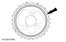
NOTE:The fuel pump pulley is sealed to the fuel pump sprocket. Remove the fuel pump pulley. | | | -
Remove the fuel pump seal. | | | -
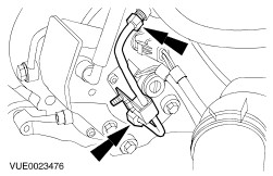
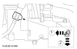
Remove the high-pressure fuel supply line support bracket. | | | -
CAUTION:The generator must be protected from contamination. Failure to follow this instruction may cause premature failure of the generator. Protect the generator with lint-free material to prevent contamination. | | | -
CAUTION:Protect the fuel metering valve and fuel temperature sensor electrical connectors to prevent contamination with the cleaning fluid. Clean the fuel pump, fuel injection supply manifold, high-pressure fuel supply line and surrounding areas.
For additional information, refer to: Fuel Injection Component Cleaning (303-04F Fuel Charging and Controls - 1.8L Diesel, Vehicles With: Common Rail Fuel Injection, General Procedures).
| | | -
CAUTION:Make sure that the high-pressure fuel supply line remains in contact with the fuel pump and the fuel injection supply manifold until all unions have been detached and cleaned. Failure to follow this instruction may result in foreign matter ingress to the fuel injection system. Detach the high pressure fuel supply line and clamp from the fuel pump and fuel injection supply manifold. | | | -
CAUTION:Make sure that the high-pressure fuel supply line remains in contact with the fuel pump and the fuel injection supply manifold until all unions have been detached and cleaned. Failure to follow this instruction may result in foreign matter ingress to the fuel injection system. Using the engine vacuum cleaner, vacuum foreign material from the high-pressure fuel supply line, the fuel pump and the fuel injection supply manifold. | | | -
Remove the high-pressure fuel supply line. | | | -
Using the engine vacuum cleaner, vacuum foreign material from the fuel pump and the fuel injection supply manifold. | | | -
Install blanking caps to the open threaded ports on the fuel pump and the fuel injection supply manifold. | | | -
NOTE:Make a note of the orientation of the clamp to make sure it is positioned in exactly the same position when installed. Remove the clamp from the high-pressure fuel supply line. | | | -
Discard the high-pressure fuel supply line. | | | -
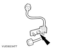
Disconnect the fuel metering valve and fuel temperature sensor electrical connectors. | | | -
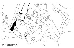
Remove the fuel pump support bracket bolts. | | | -
Disconnect the fuel pump to fuel filter fuel return line from the fuel return line venturi.
For additional information, refer to: Quick Release Coupling (310-00A Fuel System - General Information, General Procedures).
- Install blanking plugs to the fuel pump fuel return line and the fuel return line venturi.
| | | -
Disconnect the fuel pump fuel supply line from the fuel pump.
For additional information, refer to: Quick Release Coupling (310-00A Fuel System - General Information, General Procedures).
- Install blanking plugs to the fuel pump fuel supply line and the fuel pump.
| | | -
Disconnect the fuel injector fuel return line from the fuel return line venturi. - Install blanking plugs to the fuel injector fuel return line and the fuel return line venturi.
| | | -
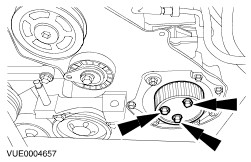
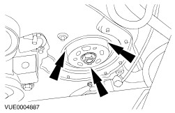
Remove the fuel pump sprocket retaining bolts. | | | -
NOTE:Access the fuel pump retaining bolts through the holes provided, however the retaining bolts cannot be removed completely. Remove the fuel pump and shield. | | | -
Remove the fuel pump shield from the fuel pump. | Installation WARNING:Do not smoke or carry lighted tobacco or open flame of any type when working on or near any fuel related components. Highly flammable mixtures are always present and may ignite. Failure to follow these instructions may result in personal injury. WARNING:This procedure involves fuel handling. Be prepared for fuel spillage at all times and always observe fuel handling precautions. Failure to follow these instructions may result in personal injury. CAUTION:Make sure the workshop area in which the vehicle is being worked on is as clean and as dust free as possible. Foreign matter from work on clutches, brakes or from machining or welding operations can contaminate the fuel system and may result in later malfuction. CAUTION:Always carry out the cleaning process before carrying out any repairs to the fuel injection system components. Failure to follow this instruction may result in foreign matter ingress to the fuel injection system. CAUTION:Diesel fuel injection equipment is manufactured to very precise tolerances and fine clearances. It is therefore essential that absolute cleanliness is observed when working with these components. Always install blanking plugs to any open orifices or lines. CAUTION:Do not disassemble or clean inside the fuel pump, even with an ultrasonic cleaner. Always install a new fuel pump when required. NOTE:Install a new fuel pump gasket. NOTE:Install a new fuel pump seal. NOTE:Install a new high-pressure fuel supply line. | | -
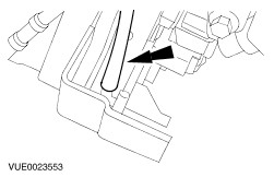
Align the hole in the fuel pump drive with the etched line on the fuel pump body. | | | -
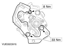
NOTE:Tighten the bolts evenly, in order to pull the fuel pump squarely into position. Install the fuel pump. | | | -
Install the fuel pump sprocket retaining bolts. | | | -
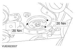
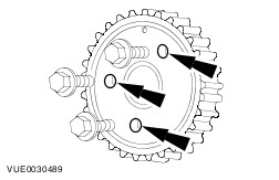
Install a new fuel pump seal. - Tighten the bolts in the sequence shown.
| | | -
Remove the blanking plugs and connect the fuel injector fuel return line to the fuel return line venturi. - Discard the blanking plugs.
| | | -
Remove the blanking plugs and connect the fuel pump fuel supply line to the fuel pump.
For additional information, refer to: Quick Release Coupling (310-00A Fuel System - General Information, General Procedures).
- Discard the blanking plugs.
| | | -
Install the fuel pump shield to the fuel pump (fuel pump shown removed for clarity). | | | -
Connect the fuel metering valve and fuel temperature sensor electrical connectors. | | | -
NOTE:Make sure the clamp is installed in the same position as removed. Install the high-pressure fuel supply line clamp to the high-pressure fuel supply line. | | | -
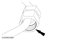
Using a suitable multipurpose lubricant spray, lubricate the high-pressure fuel supply line union threads. | | | -
CAUTION:The generator must be protected from contamination. Failure to follow this instruction may cause premature failure of the generator. Protect the generator with lint-free material to prevent contamination. | | | -
CAUTION:Do not allow the unions to hit the ends of the high-pressure fuel supply line. Failure to follow this instruction may result in damage to the ends of the line and allow foreign matter to enter the fuel injection system. CAUTION:Remove the blanking plugs from the high-pressure fuel supply line, the fuel pump and the fuel injection supply manifold at the last possible moment. Failure to follow this instruction may result in foreign matter ingress to the fuel injection system. NOTE:Do not tighten the high-pressure fuel supply line unions at this stage. NOTE:Maintain pressure on the high-pressure fuel supply line to keep the line in contact with the fuel pump and fuel injection supply manifold cones while installing the unions. Install a new high-pressure fuel supply line. - Install the high-pressure fuel supply line union to the fuel injection supply manifold.
- Install the high-pressure fuel supply line union to the fuel pump.
- Discard the blanking plugs.
| | | -
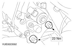
Tighten the fuel pump support bracket bolts (high-pressure fuel supply line shown removed for clarity). | | | -
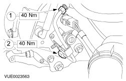
CAUTION:Make sure the tool used to tighten the high-pressure fuel supply line unions is used at the top of the union as this is where there is most material. Failure to follow this instruction may result in damage to the union. Tighten the high-pressure fuel supply line unions. - Tighten the high-pressure fuel supply line union at the fuel injection supply manifold.
- Tighten the high-pressure fuel supply line union at the fuel pump.
| | | -
Install the high-pressure fuel supply line bracket. | | | -
Connect the fuel pump to fuel filter fuel return line.
For additional information, refer to: Quick Release Coupling (310-00A Fuel System - General Information, General Procedures).
| | | -
Using sealant, seal the fuel pump pulley to the fuel pump sprocket. | | | -
Apply sealant to the outer edge of the fuel pump pulley bolt holes. | | | -
Install the fuel pump pulley. | | | -
Remove the lint-free material from the generator. | | | -
Install a new timing belt.
For additional information, refer to: Timing Belt (303-01C Engine - 1.8L Diesel, In-vehicle Repair).
| | | -
Install a new fuel filter.
For additional information, refer to: Fuel Filter - 1.8L Diesel, Vehicles With: Common Rail Fuel Injection (310-01A Fuel Tank and Lines, Removal and Installation).
| | |