| Diagnosis and Testing Refer to Wiring Diagrams Section 413-00, for schematic and connector information. Principles of Operation NOTE:A new instrument cluster must be reconfigured.
REFER to: Module Configuration (418-01 Module Configuration, General Procedures).
The instrument cluster and panel illumination consists of dimmable and non-dimmable illumination. The dimmable panel illumination is controlled by the panel illumination switch (part of the headlamp switch), which allows the brightness level of the backlights to be adjusted dependent on the customer preference. When the headlamp switch is in the parking lamps ON or headlamps ON position, the intensity of the backlighting can be adjusted using the panel dimmer switch. The non dimmable illumination allows for full intensity dependant on the ignition switch position. Instrument Cluster and Dimmable Backlighting The dimmable illumination utilizes both conventional illumination bulbs and LEDs. The following dimmable components are backlit using conventional illumination bulbs: - ashtray
- cigar lighter
- transmission control lever
- base instrument cluster (except vehicles with 2.0L Duratec ST)
- heater control panel
The following dimmable components are backlit using LEDs: - audio unit
- instrument cluster
- oil pressure and oil temperature cluster
- climate control assembly
- hazard switch
- traction control system disable switch
- right-hand and left-hand heated front seat switches
CAUTION:The 2.0L Duratec ST instrument cluster utilizes high AC voltage for the electro-luminescent backlighting system in both instrument clusters. Care must be exercised when taking measurements of the instrument cluster circuits. The instrument cluster backlight utilizes two cluster configurations, the base instrument cluster and the 2.0L Duratec ST instrument cluster(s) configuration. The base configuration uses conventional illumination bulbs and the 2.0L Duratec ST instrument cluster(s) configuration uses an electro-luminescent backlight strategy. The electro-luminescent backlighting utilizes switched DC to high AC voltage circuitry. The oil pressure and oil temperature cluster converts 12V DC into AC voltage that is variable up to 180V AC through the dimmer switch (part of the headlamp switch) control. The high voltage AC current is sent to the base cluster through a hardwired circuit. These circuits are labeled "High Voltage" at both clusters. Non-Dimmable Backlighting The headlamp switch backlighting consists of two constantly illuminated LED bulbs that are powered by separate circuits. Battery power is supplied to the first bulb when the ignition is in the RUN position. Battery power is supplied to the second bulb when the headlamp switch is placed in the headlamps ON or the parking lamps ON position. Inspection and Verification - Verify the customer concern.
- Visually inspect for obvious signs mechanical or electrical damage.
Visual Inspection Chart | Mechanical | Electrical | - Engine/engine compartment or underbody components
- Fluid levels
- Accessory installation
| - Fuse(s)
- Loose or corroded connector(s)
- Instrument cluster(s)
- Oil pressure and oil temperature cluster
- Wiring Harness
- Circuit
- Bulbs
| - If an obvious cause for an observed or reported concern is found, correct the cause (if possible) before proceeding to the next step.
- If the cause is not visually evident, verify the symptom and refer to the Symptom Chart.
Symptom Chart Symptom Chart | Symptom | Possible Sources | Action | | The control illumination is inoperative | * Fuse. * Headlamp switch. * Circuit. | * | | The Instrument cluster illumination is inoperative | * Circuit. * Instrument cluster. * Oil pressure and oil temperature cluster . * Trip computer. | * | | The climate control illumination is inoperative | * Circuit. * Climate control panel illumination lamp. | * | | The audio system illumination is inoperative | * Circuit. * Audio control unit. | * | | The navigation system illumination is inoperative | * Circuit. * Navigation system display module. | * | | The gearshift illumination is inoperative. | * Circuit. * Gearshift illumination bulb socket. | * | | The cigar lighter illumination is inoperative. | * Circuit. * Cigar lighter socket. | * | | The traction control switch illumination is inoperative. | * Circuit. * Traction control switch. | * | | The hazard switch illumination is inoperative. | * Circuit. * Hazard switch. | * | | The front seat heater switch illumination is inoperative. | * Circuit. * Front seat heater switch. | * | | The instrument panel illumination does not dim. | * Dimmer switch. | * INSTALL a new headlamp/dimmer switch unit. | | The ashtray illumination is inoperative. | * Circuit. * Ashtray illumination lamp. | * | | The clock illumination is inoperative | * Circuit. * Clock. | * | | The heater control module illumination is inoperative | * Circuit. * Heater control module. | * | | The power window control switch(es) illumination is inoperative | * Circuit. * Power window control switch(es). | * | Pinpoint Tests | PINPOINT TEST A : THE CONTROL ILLUMINATION IS INOPERATIVE | | TEST CONDITIONS | DETAILS/RESULTS/ACTIONS | | A1: CHECK PARKING LAMP OPERATION | | | 1 Ignition switch in position 0. | | | 2 Place the side lamps in the ON position. | | | Do the side lamps and license plate lamps illuminate? Yes INSTALL a new headlamp switch. TEST the system for normal operation. No CHECK fuse 32 (10A). If the fuse is OK then diagnose exterior lighting.
REFER to: Parking, Rear and License Lamps - Vehicles Built Up To: 08/2001 (417-01 Exterior Lighting, Diagnosis and Testing).
or
REFER to: Parking, Rear and License Lamps - Vehicles Built From: 08/2001 (417-01 Exterior Lighting, Diagnosis and Testing).
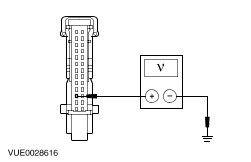
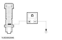
If the fuse has failed, INSTALL a new fuse. TEST the system for normal operation. If the fuse fails again, CHECK for a short to ground, REPAIR as necessary. | | PINPOINT TEST B : THE INSTRUMENT CLUSTER ILLUMINATION IS INOPERATIVE | | TEST CONDITIONS | DETAILS/RESULTS/ACTIONS | | B1: CHECK THE INSTRUMENT CLUSTER ILLUMINATION | | | 1 Place the headlamp switch in the headlamps ON position. | | | Is only the instrument cluster illumination inoperative? Yes Place the headlamp switch in the OFF position. GO to B2. On vehicles with 2.0L Duratec ST, if the oil pressure and oil temperature cluster illumination is inoperative. GO to B4. On vehicles without 2.0L Duratec ST, if the trip computer illumination is inoperative. GO to B7. No If the exterior lighting is inoperative, REFER to: Headlamps - Vehicles Built Up To: 08/2001 (417-01 Exterior Lighting, Diagnosis and Testing). or REFER to: Headlamps - Vehicles Built From: 08/2001 (417-01 Exterior Lighting, Diagnosis and Testing). If all of the control illumination is inoperative, GO to Pinpoint Test A. | | B2: CHECK CIRCUIT 29S-GG14 (OG) FOR VOLTAGE | | | 1 Ignition switch in position 0. | | | 2 Disconnect Instrument Cluster C809. | | | 3 Make sure that the illumination dimmer switch is in the full illumination position. | | | 4 Place the headlamp switch in the headlamp ON position. | | | 5 Measure the voltage between the instrument cluster C809 pin 3, circuit 29S-GG14 (OG), harness side and ground. | | | Is the voltage greater than 10 volts? Yes No REPAIR the circuit. TEST the system for normal operation. | | B3: CHECK CIRCUIT 91-GG14 (BK/OG) FOR OPEN | | | 1 Place the headlamp switch in the OFF position. | | | 2 Measure the resistance between instrument cluster C809 pin 2 circuit 91-GG14 (BK/OG), harness side and ground. | | | Is the resistance less than 1 ohm? Yes CHECK the condition of the bulbs. INSTALL new bulbs as necessary. If bulbs OK then INSTALL a new instrument cluster.
REFER to: Instrument Cluster (413-01 Instrument Cluster, Removal and Installation).
or
REFER to: Instrument Cluster - 2.0L Duratec-ST (Zetec) (413-01 Instrument Cluster, Removal and Installation).
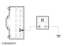
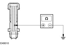
TEST the system for normal operation. No REPAIR the circuit. TEST the system for normal operation. | | B4: CHECK THE OIL PRESSURE AND OIL TEMPERATURE CLUSTER ILLUMINATION | NOTE:The oil pressure and oil temperature cluster illumination wiring harness is connected through the main instrument cluster illumination wiring harness. If the main instrument cluster illumination has a concern then the oil pressure and oil temperature cluster may also be inoperative. CHECK the main instrument cluster illumination circuit before attempting to diagnose the oil pressure and oil temperature cluster illumination. | | | 1 Place the headlamp switch in the headlamps ON position. | | | Is only the oil pressure and oil temperature cluster illumination inoperative? Yes Place the headlamp switch in the OFF position. GO to B5. No If the exterior lighting is inoperative, REFER to: Headlamps - Vehicles Built Up To: 08/2001 (417-01 Exterior Lighting, Diagnosis and Testing). or REFER to: Headlamps - Vehicles Built From: 08/2001 (417-01 Exterior Lighting, Diagnosis and Testing). If all of the control illumination is inoperative, GO to Pinpoint Test A. | | B5: CHECK CIRCUIT 29S-GE6A (OG/YE) FOR VOLTAGE | | | 1 Ignition switch in position 0. | | | 2 Disconnect Oil Pressure And Oil Temperature Cluster C853. | | | 3 Make sure that the illumination dimmer switch is in the full illumination position. | | | 4 Place the headlamp switch in the headlamp ON position. | | | 5 Measure the voltage between the oil pressure and oil temperature cluster C853 pin 15 (left-hand drive) or pin 10 (right-hand drive), circuit 29S-GE6A (OG/YE), harness side and ground. | | | Is the voltage greater than 10 volts? Yes No REPAIR the circuit. TEST the system for normal operation. | | B6: CHECK CIRCUIT 91-GE6 (BK/YE) FOR OPEN | | | 1 Place the headlamp switch in the OFF position. | | | 2 Measure the resistance between the oil pressure and oil temperature cluster C853 pin 16 (left-hand drive) or pin 9 (right-hand drive), circuit 91-GE6 (BK/YE), harness side and ground. | | | Is the resistance less than 1 ohm? Yes CHECK the condition of the bulbs. INSTALL new bulbs as necessary. If bulbs OK then INSTALL a new oil pressure and oil temperature cluster.
REFER to: Oil Pressure and Oil Temperature Cluster - 2.0L Duratec-ST (Zetec) (413-01 Instrument Cluster, Removal and Installation).
TEST the system for normal operation. No REPAIR the circuit. TEST the system for normal operation. | | B7: CHECK CIRCUIT 29S-GE6A (OG/YE) FOR VOLTAGE | | | 1 Ignition switch in position 0. | | | 2 Disconnect Trip Computer C467. | | | 3 Make sure that the illumination dimmer switch is in the full illumination position. | | | 4 Place the headlamp switch in the headlamp ON position. | | | 5 Measure the voltage between the trip computer C467 pin 21, circuit 29S-GE6A (OG/YE), harness side and ground. | | | Is the voltage greater than 10 volts? Yes No REPAIR the circuit. TEST the system for normal operation. | | B8: CHECK CIRCUIT 91-GE6 (BK/YE) FOR OPEN | | | 1 Place the headlamp switch in the OFF position. | | | 2 Measure the resistance between the instrument cluster C467 pin 20, circuit 91-GE6 (BK/YE), harness side and ground. | | | Is the resistance less than 1 ohm? Yes CHECK the condition of the bulbs. INSTALL new bulbs as necessary. If bulbs OK then INSTALL a new trip computer. TEST the system for normal operation. No REPAIR the circuit. TEST the system for normal operation. | | PINPOINT TEST C : THE CLIMATE CONTROL ILLUMINATION IS INOPERATIVE | | TEST CONDITIONS | DETAILS/RESULTS/ACTIONS | | C1: CHECK CIRCUIT 29S-LH27 (OG/GN) FOR VOLTAGE | | | 1 Ignition switch in position 0. | | | 2 Disconnect Climate Control Illumination Lamp C493. | | | 3 Make sure that the illumination dimmer switch is in the full illumination position. | | | 4 Place the headlamp switch in the ON position. | | | 5 Measure the voltage between the climate control panel illumination lamp C493 pin 2, circuit 29S-LH27 (OG/GN), harness side and ground. | | | Is the voltage greater than 10 volts? Yes No REPAIR the circuit. TEST the system for normal operation. | | C2: CHECK CIRCUIT 31-LH27 (BK) FOR OPEN | | | 1 Place the headlamp switch in the OFF position. | | | 2 Measure the resistance between the climate control panel illumination lamp C493 pin 1 circuit 31-LH27 (BK), harness side and ground. | | | Is the resistance less than 1 ohm? Yes INSTALL a new climate control panel illumination lamp. TEST the system for normal operation. No REPAIR the circuit. TEST the system for normal operation. | | PINPOINT TEST D : THE AUDIO SYSTEM ILLUMINATION IS INOPERATIVE | | TEST CONDITIONS | DETAILS/RESULTS/ACTIONS | | D1: CHECK VOLTAGE TO THE AUDIO UNIT BULBS CIRCUIT 29S-LK34 (OG/BU) | | | 1 Ignition switch in position 0. | | | 2 Disconnect Audio Unit C443 or C446. | | | 3 Make sure that the illumination dimmer switch is in the full illumination position. | | | 4 Place the headlamp switch in the headlamps ON position. | | | 5 Measure the voltage between the audio unit C443 or C446 pin 4, circuit 29S-LK34 (OG/BK), harness side and ground. | | | Is the voltage greater than 10 volts? Yes No REPAIR the circuit. TEST the system for normal operation. | | D2: CHECK CIRCUIT 91-MD34 (BK/YE) FOR OPEN | | | 1 Place the headlamp switch in the OFF position. | | | 2 Measure the resistance between the audio unit C443 or C446 pin 2, circuit 91-MD34 (BK/YE), harness side and ground | | | Is the resistance less than 1 ohm? Yes INSTALL a new audio Unit.
REFER to: Audio Unit (415-01 Audio Unit, Removal and Installation).
TEST the system for normal operation. No REPAIR the circuit. TEST the system for normal operation. | | PINPOINT TEST E : THE NAVIGATION SYSTEM ILLUMINATION IS INOPERATIVE | | TEST CONDITIONS | DETAILS/RESULTS/ACTIONS | | E1: CHECK CIRCUIT 29S-LK34 (OG/BK) FOR VOLTAGE | | | 1 Ignition switch in position 0. | | | 2 Disconnect Navigation System Display Module C505. | | | 3 Make sure that the illumination dimmer switch is in the full illumination position. | | | 4 Place the headlamp switch in the headlamps ON position. | | | 5 Measure the voltage between the navigation system display module C505 pin 6, circuit 29S-LK34 (OG/BK), harness side and ground. | | | Is the voltage greater than 10 volts? Yes No REPAIR the circuit. TEST the system for normal operation. | | E2: CHECK CIRCUIT 91-MD34 (BK/YE) FOR OPEN | | | 1 Place the headlamp switch in the OFF position. | | | 2 Disconnect Navigation System Display Module C507. | | | 3 Measure the resistance between the navigation system display module C507 pin 5, circuit 91-MD34 (BK/YE), harness side and ground. | | | Is the resistance less than 1 ohm? Yes INSTALL a new navigation system display module. TEST the system for normal operation. No REPAIR the circuit. TEST the system for normal operation. | | PINPOINT TEST F : THE GEARSHIFT ILLUMINATION IS INOPERATIVE | | TEST CONDITIONS | DETAILS/RESULTS/ACTIONS | | F1: CHECK CIRCUIT 29S-LK21 (OG/BK) FOR VOLTAGE | | | 1 Disconnect Gearshift Lever C931. | | | 2 Make sure that the illumination dimmer switch is in the full illumination position. | | | 3 Place the headlamp switch in the headlamps ON position. | | | 4 Measure the voltage between the gearshift lever C931 pin 4, circuit 29S-LK21 (OG/BK), harness side and ground. | | | Is the voltage greater than 10 volts? Yes No REPAIR the circuit. TEST the system for normal operation. | | F2: CHECK CIRCUIT 31-TA34 (BK) FOR OPEN | | | 1 Place the headlamp switch in the OFF position. | | | 2 Measure the resistance between the gearshift lever C931 pin 1, circuit 31-TA34 (BK), harness side and ground. | | | Is the resistance less than 1 ohm? Yes INSTALL a new gearshift illumination bulb socket. TEST the system for normal operation. No REPAIR the circuit. TEST the system for normal operation. | | PINPOINT TEST G : THE CIGAR LIGHTER ILLUMINATION IS INOPERATIVE | | TEST CONDITIONS | DETAILS/RESULTS/ACTIONS | | G1: CHECK CIRCUIT 29S-LK15 (OG) FOR VOLTAGE | | | 1 Disconnect Cigar Lighter C911. | | | 2 Make sure that the illumination dimmer switch is in the full illumination position. | | | 3 Place the headlamp switch in the headlamp ON position. | | | 4 Measure the voltage between the cigar lighter C911 pin 1, circuit 29S-LK15 (OG), harness side and ground. | | | Is the voltage greater than 10 volts? Yes No REPAIR the circuit. TEST the system for normal operation. | | G2: CHECK CIRCUIT 31-HA6 (BK) FOR OPEN | | | 1 Place the headlamp switch in the OFF position. | | | 2 Disconnect Cigar Lighter C912. | | | 3 Measure the resistance between the cigar lighter C912 pin 1, circuit 31-HA6 (BK), harness side and ground. | | | Is the resistance less than 1 ohm? Yes INSTALL a new cigar lighter socket. TEST the system for normal operation. No REPAIR the circuit. TEST the system for normal operation. | | PINPOINT TEST H : THE TRACTION CONTROL SWITCH ILLUMINATION IS INOPERATIVE | | TEST CONDITIONS | DETAILS/RESULTS/ACTIONS | | H1: CHECK CIRCUIT 29S-LH45 (OG/WH) FOR VOLTAGE | | | 1 Disconnect Traction Control Switch C717. | | | 2 Make sure that the illumination dimmer switch is in the full illumination position. | | | 3 Place the headlamp switch in the ON position. | | | 4 Measure the voltage between the traction control switch C717 pin 8 circuit 29S-LH45 (OG/WH) harness side and ground. | | | Is the voltage greater than 10 volts? Yes No REPAIR the circuit. TEST the system for normal operation. | | H2: CHECK CIRCUIT 91-LH45 (BK/WH) FOR OPEN | | | 1 Place the headlamp switch in the OFF position. | | | 2 Measure the resistance between the traction control switch C717 pin 7 circuit 91-LH45 (BK/WH), harness side and ground. | | | Is the resistance less than 1 ohm? Yes INSTALL a new traction control disable switch. TEST the system for normal operation. No REPAIR the circuit. TEST the system for normal operation. | | PINPOINT TEST I : THE HAZARD SWITCH ILLUMINATION IS INOPERATIVE | | TEST CONDITIONS | DETAILS/RESULTS/ACTIONS | | I1: CHECK THE OPERATION OF THE HAZARD SWITCH | | | 1 Operate the hazard switch. | | | Does the turn signal and hazard lamps illuminate? Yes Vehicles built 08/2001 onwards, GO to I4. No REFER to: Turn Signal and Hazard Lamps - Vehicles Built Up To: 08/2001 (417-01 Exterior Lighting, Diagnosis and Testing). or
REFER to: Turn Signal and Hazard Lamps - Vehicles Built From: 08/2001 (417-01 Exterior Lighting, Diagnosis and Testing).
| | I2: CHECK CIRCUIT 29S-LG8A (OG) FOR VOLTAGE | | | 1 Disconnect Hazard Switch C458. | | | 2 Make sure that the illumination dimmer switch is in the full illumination position. | | | 3 Place the headlamp switch in the ON position. | | | 4 Measure the voltage between the hazard switch C458 pin 4, circuit 29S-LG8A (OG), harness side and ground. | | | Is the voltage greater than 10 volts? Yes No REPAIR the circuit. TEST the system for normal operation. | | I3: CHECK CIRCUIT 91-LG8 (BK/OG) FOR OPEN | | | 1 Place the headlamp switch in the OFF position. | | | 2 Measure the resistance between the hazard switch C458 pin 10 circuit 91-LG8 (BK/OG), harness side and ground. | | | Is the resistance less than 1 ohm? Yes INSTALL a new hazard switch. TEST the system for normal operation. No REPAIR the circuit. TEST the system for normal operation. | | I4: CHECK CIRCUIT 29S-LH54 (OG/GN) FOR VOLTAGE | | | 1 Disconnect Hazard Switch C458. | | | 2 Make sure that the illumination dimmer switch is in the full illumination position. | | | 3 Place the headlamp switch in the ON position. | | | 4 Measure the voltage between the hazard switch C458 pin 6, circuit 29S-LH54 (OG/GN), harness side and ground. | | | Is the voltage greater than 10 volts? Yes No REPAIR the circuit. TEST the system for normal operation. | | I5: CHECK CIRCUIT 91-LG8 (BK/OG) FOR OPEN | | | 1 Place the headlamp switch in the OFF position. | | | 2 Measure the resistance between the hazard switch C458 pin 5 circuit 91-LG8 (BK/OG), harness side and ground. | | | Is the resistance less than 1 ohm? Yes INSTALL a new hazard switch. TEST the system for normal operation. No REPAIR the circuit. TEST the system for normal operation. | | PINPOINT TEST J : THE FRONT SEAT HEATER SWITCH ILLUMINATION IS INOPERATIVE | | TEST CONDITIONS | DETAILS/RESULTS/ACTIONS | | J1: CHECK INOPERATIVE SEAT HEATER SWITCH FOR VOLTAGE | | | 1 Disconnect Inoperative Seat Heater Switch. | | | 2 Make sure that the illumination dimmer switch is in the full illumination position. | | | 3 Place the headlamp switch in the ON position. | | | 4 Measure the voltage between the seat heater switch C694 (LH) pin 8 circuit 29S-LH29 (OG/YE), harness side and ground: or C695 (RH) pin 8 circuit 29S-LH43 (OG/BU), harness side and ground. | | | Is the voltage greater than 10 volts? Yes No REPAIR circuit 29S-LH29 (OG/YE) or circuit 29S-LH43 (OG/BU) aa necessary. TEST the system for normal operation. | | J2: CHECK GROUND TO INOPERATIVE SEAT HEATER SWITCH FOR OPEN | | | 1 Place the headlamp switch in the OFF position. | | | 2 Measure the resistance between the seat heater switch C694 (LH) pin 4 circuit 31-LH29 (BK), harness side and ground; or the seat heater switch C695 (RH) pin 4 circuit 31-LH43 (BK), harness side and ground. | | | Is the resistance less than 1 ohm? Yes INSTALL a new seat heater switch. TEST the system for normal operation. No REPAIR circuit 31-LH29 (BK) or circuit 31-LH43 (BK) as necessary. TEST the system for normal operation. | | PINPOINT TEST K : THE ASHTRAY ILLUMINATION IS INOPERATIVE | | TEST CONDITIONS | DETAILS/RESULTS/ACTIONS | | K1: CHECK CIRCUIT 29S-LA16 (OG/YE) FOR VOLTAGE | | | 1 Disconnect Ashtray C913. | | | 2 Make sure that the illumination dimmer switch is in the full illumination position. | | | 3 Place the headlamp switch in the ON position. | | | 4 Measure the voltage between the ashtray C913 pin 1, circuit 29S-LA16 (OG/YE), harness side and ground. | | | Is the voltage greater than 10 volts? Yes No REPAIR the circuit. TEST the system for normal operation. | | K2: CHECK CIRCUIT 31-LA16 (BK) FOR OPEN | | | 1 Place the headlamp switch in the OFF position. | | | 2 Measure the resistance between the ashtray C913 pin 2, circuit 31-LA16 (BK), harness side and ground. | | | Is the resistance less than 1 ohm? Yes INSTALL a new ashtray illumination lamp. TEST the system for normal operation. No REPAIR the circuit. TEST the system for normal operation. | | PINPOINT TEST L : THE CLOCK ILLUMINATION IS INOPERATIVE | | TEST CONDITIONS | DETAILS/RESULTS/ACTIONS | | L1: CHECK CIRCUIT 29S-LK16 (OG/YE) FOR VOLTAGE | | | 1 Disconnect Clock C460. | | | 2 Make sure that the illumination dimmer switch is in the full illumination position. | | | 3 Place the headlamp switch in the ON position. | | | 4 Measure the voltage between the clock C460 pin 4, circuit 29S-LK16 (OG/YE), harness side and ground. | | | Is the voltage greater than 10 volts? Yes No REPAIR the circuit. TEST the system for normal operation. | | L2: CHECK CIRCUIT 91-GB6 (BK/YE) FOR OPEN | | | 1 Place the headlamp switch in the OFF position. | | | 2 Measure the resistance between the clock C460 pin 2, circuit 91-GB6 (BK/YE), harness side and ground. | | | Is the resistance less than 1 ohm? Yes INSTALL a new clock. TEST the system for normal operation. No REPAIR the circuit. TEST the system for normal operation. | | PINPOINT TEST M : THE HEATER CONTROL MODULE ILLUMINATION IS INOPERATIVE | | TEST CONDITIONS | DETAILS/RESULTS/ACTIONS | | M1: CHECK CIRCUIT 29S-LE10 (OG/GN) FOR VOLTAGE | | | 1 Disconnect Heater Control Module C380. | | | 2 Make sure that the illumination dimmer switch is in the full illumination position. | | | 3 Place the headlamp switch in the ON position. | | | 4 Measure the voltage between the heater control module C380 pin 2, circuit 29S-LE10 (OG/GN), harness side and ground. | | | Is the voltage greater than 10 volts? Yes No REPAIR the circuit. TEST the system for normal operation. | | M2: CHECK CIRCUIT 91-FA13 (BK/OG) FOR OPEN | | | 1 Place the headlamp switch in the OFF position. | | | 2 Measure the resistance between the heater control module C460 pin 12, circuit 91-FA13 (BK/OG), harness side and ground. | | | Is the resistance less than 1 ohm? Yes INSTALL a new heater control module. TEST the system for normal operation. No REPAIR the circuit. TEST the system for normal operation. | | PINPOINT TEST N : THE POWER WINDOW CONTROL SWITCH(ES) ILLUMINATION IS INOPERATIVE | | TEST CONDITIONS | DETAILS/RESULTS/ACTIONS | | N1: CHECK THE POWER WINDOW CONTROL SWITCH(ES) OPERATION | | | 1 Operate the power window control switch(es). | | | Does the power window control switch(es) operate correctly? Yes 4-door, 5-door and wagon, front driver side. GO to N6. 4-door, 5-door and wagon, front passenger side. GO to N8. 4-door, 5-door and wagon, rear right-hand side. GO to N10. 4-door, 5-door and wagon, rear left-hand side. GO to N12. No REFER to: Glass, Frames and Mechanisms - Vehicles Built Up To: 08/2000 (501-11 Glass, Frames and Mechanisms, Diagnosis and Testing).,
REFER to: Glass, Frames and Mechanisms - Vehicles Built From: 08/2000 Vehicles Built Up To: 08/2001 (501-11 Glass, Frames and Mechanisms, Diagnosis and Testing).
or
REFER to: Glass, Frames and Mechanisms - Vehicles Built From: 08/2001 (501-11 Glass, Frames and Mechanisms, Diagnosis and Testing).
| | N2: CHECK CIRCUIT 15-AJ7 (GN/BU) FOR VOLTAGE | | | 1 Disconnect Power Window Control Switch C488. | | | 2 Make sure that the illumination dimmer switch is in the full illumination position. | | | 3 Place the headlamp switch in the ON position. | | | 4 Measure the voltage between the power window control switch C488 pin 10, circuit 15-AJ7 (GN/BU), harness side and ground. | | | Is the voltage greater than 10 volts? Yes No REPAIR the circuit. TEST the system for normal operation. | | N3: CHECK CIRCUIT 31-AJ7 (BK) FOR OPEN | | | 1 Place the headlamp switch in the OFF position. | | | 2 Measure the resistance between the power window control switch C488 pin 1, circuit 31-AJ7 (BK), harness side and ground. | | | Is the resistance less than 1 ohm? Yes INSTALL a new power window control switch. TEST the system for normal operation. No REPAIR the circuit. TEST the system for normal operation. | | N4: CHECK CIRCUIT 15-AJ18 (GN/WH) FOR VOLTAGE | | | 1 Disconnect Power Window Control Switch C489. | | | 2 Make sure that the illumination dimmer switch is in the full illumination position. | | | 3 Place the headlamp switch in the ON position. | | | 4 Measure the voltage between the power window control switch C489 pin 2, circuit 15-AJ18 (GN/WH), harness side and ground. | | | Is the voltage greater than 10 volts? Yes No REPAIR the circuit. TEST the system for normal operation. | | N5: CHECK CIRCUIT 31-LH31 (BK) FOR OPEN | | | 1 Place the headlamp switch in the OFF position. | | | 2 Measure the resistance between the power window control switch C489 pin 4, circuit 31-LH31 (BK), harness side and ground. | | | Is the resistance less than 1 ohm? Yes INSTALL a new power window control switch. TEST the system for normal operation. No REPAIR the circuit. TEST the system for normal operation. | | N6: CHECK CIRCUIT 15-AJ14 (GN/YE) FOR VOLTAGE | | | 1 Disconnect Power Window Control Switch C484. | | | 2 Make sure that the illumination dimmer switch is in the full illumination position. | | | 3 Place the headlamp switch in the ON position. | | | 4 Measure the voltage between the power window control switch C484 pin 13, circuit 15-AJ14 (GN/YE), harness side and ground. | | | Is the voltage greater than 10 volts? Yes No REPAIR the circuit. TEST the system for normal operation. | | N7: CHECK CIRCUIT 31-AJ7 (BK) FOR OPEN | | | 1 Place the headlamp switch in the OFF position. | | | 2 Measure the resistance between the power window control switch C484 pin 4, circuit 31-AJ7 (BK), harness side and ground. | | | Is the resistance less than 1 ohm? Yes INSTALL a new power window control switch. TEST the system for normal operation. No REPAIR the circuit. TEST the system for normal operation. | | N8: CHECK CIRCUIT 15-LH31 (GN/BU) FOR VOLTAGE | | | 1 Disconnect Power Window Control Switch C485. | | | 2 Make sure that the illumination dimmer switch is in the full illumination position. | | | 3 Place the headlamp switch in the ON position. | | | 4 Measure the voltage between the power window control switch C485 pin 1, circuit 15-LH31 (GN/BU), harness side and ground. | | | Is the voltage greater than 10 volts? Yes No REPAIR the circuit. TEST the system for normal operation. | | N9: CHECK CIRCUIT 31-AJ18 (BK) FOR OPEN | | | 1 Place the headlamp switch in the OFF position. | | | 2 Measure the resistance between the power window control switch C485 pin 6, circuit 31-AJ18 (BK), harness side and ground. | | | Is the resistance less than 1 ohm? Yes INSTALL a new power window control switch. TEST the system for normal operation. No REPAIR the circuit. TEST the system for normal operation. | | N10: CHECK CIRCUIT 15-LH36 (GN/RD) FOR VOLTAGE | | | 1 Disconnect Power Window Control Switch C482b. | | | 2 Make sure that the illumination dimmer switch is in the full illumination position. | | | 3 Place the headlamp switch in the ON position. | | | 4 Measure the voltage between the power window control switch C482b pin 1, circuit 15-LH36 (GN/RD), harness side and ground. | | | Is the voltage greater than 10 volts? Yes No REPAIR the circuit. TEST the system for normal operation. | | N11: CHECK CIRCUIT 31S-AJ32 (BK/OG) FOR OPEN | | | 1 Place the headlamp switch in the OFF position. | | | 2 Measure the resistance between the power window control switch C482b pin 6, circuit 31S-AJ32 (BK/OG), harness side and ground. | | | Is the resistance less than 1 ohm? Yes INSTALL a new power window control switch. TEST the system for normal operation. No REPAIR the circuit. TEST the system for normal operation. If the concern persists, INSTALL a new front driver side power window control switch. TEST the system for normal operation. | | N12: CHECK CIRCUIT 15-LH36 (GN/RD) FOR VOLTAGE | | | 1 Disconnect Power Window Control Switch C482a. | | | 2 Make sure that the illumination dimmer switch is in the full illumination position. | | | 3 Place the headlamp switch in the ON position. | | | 4 Measure the voltage between the power window control switch C482a pin 1, circuit 15-LH36 (GN/RD), harness side and ground. | | | Is the voltage greater than 10 volts? Yes No REPAIR the circuit. TEST the system for normal operation. | | N13: CHECK CIRCUIT 31S-AJ32 (BK/OG) FOR OPEN | | | 1 Place the headlamp switch in the OFF position. | | | 2 Measure the resistance between the power window control switch C482a pin 6, circuit 31S-AJ32 (BK/OG), harness side and ground. | | | Is the resistance less than 1 ohm? Yes INSTALL a new power window control switch. TEST the system for normal operation. No REPAIR the circuit. TEST the system for normal operation. If the concern persists, INSTALL a new front driver side power window control switch. TEST the system for normal operation. | |