| Diagnosis and Testing Refer to Wiring Diagrams Section 414-02, for schematic and connector information. Surface charge dissipation unit (SCD²) Micro390 battery tester Inspection and Verification WARNING:Batteries contain sulphuric acid. Avoid contact with skin, eyes, or clothing. Also, shield your eyes when working near batteries to protect against possible splashing of the acid solution. In case of acid contact with skin or eyes, flush immediately with water for a minimum of 15 minutes and get prompt medical attention. If acid is swallowed, call a physician immediately. Failure to follow these instructions may result in personal injury. WARNING:Batteries normally produce explosive gases which can cause personal injury. Therefore, do not allow flames, sparks or lighted substances to come near the battery. When charging or working near a battery, always shield your face and protect your eyes. Always provide ventilation. Failure to follow these instructions may result in personal injury. - Verify the customer concern.
- Visually inspect for obvious signs of mechanical and electrical damage.
Visual Inspection Chart | Mechanical | Electrical | - Accessory drive belt
- Generator
- Generator decoupler
- Hardware
| - Fuse 10 (10A)
- Wiring harness
- Electrical connector(s)
- Battery
- Battery cable(s)
- PCM
- Communications link to PCM
| - If an obvious cause for an observed or reported concern is found, correct the cause (if possible) before proceeding to the next step.
- Check the operation of the charging system warning indicator lamp, located in the instrument cluster. Normal operation is as follows:
Normal Charging System Voltages | Ignition Switch Position | I Circuit | Generator B+ Circuit | Battery | Engine to battery ground | Charging System Warning Indicator Operation | | Position 0 | 0V | 10-12V | 10-12V | 0V | OFF | | Position II | 0V | 10-12V | 10-12V | 0V | Illuminated | | Position II with the engine running | 13-15V | 13-15V | 13-15V | 0V | OFF | - If the cause is not visually evident, verify the symptom and refer to the Symptom Chart.
| Symptom | Possible Sources | Action | | The charging system warning indicator is on with the engine running | * Accessory drive belt. | * CHECK the accessory drive belt condition,
REFER to: Accessory Drive (303-05 Accessory Drive, Diagnosis and Testing).
| | * Generator decoupler (vehicles with 1.8L diesel engine). | * CARRY out the Generator Decoupler Component Test,
REFER to: Accessory Drive (303-05 Accessory Drive, Diagnosis and Testing).
| | * Fuse 10 (10A). * Circuit. * Generator. * Battery. * Battery ground cable. | * | | The charging system warning indicator is off with the ignition switch in the RUN position and the engine off | * Bulb. * Circuit. * Generator. | * All except 2.0L Duratec RS engine,
REFER to: Instrument Cluster - Vehicles Built Up To: 08/2001 (413-01 Instrument Cluster, Diagnosis and Testing).
or vehicles with 2.0L Duratec RS engine,
REFER to: Instrument Cluster - 2.0L Duratec-RS (Zetec) (413-01 Instrument Cluster, Diagnosis and Testing).
| | Radio interference | * Circuit. * Generator. | * | | The system overcharges | * Generator. | * INSTALL a new generator.
REFER to: Generator - 1.6L Zetec-SE (Sigma)/1.4L (414-02 Generator and Regulator, Removal and Installation) /
Generator - 1.6L Zetec-E (Zetec)/1.8L/2.0L/2.0L Duratec-RS (Zetec) (414-02 Generator and Regulator, Removal and Installation) /
Generator - 1.8L Diesel (414-02 Generator and Regulator, Removal and Installation).
| | The Generator is Noisy | * Accessory drive belt. | * REFER to: Accessory Drive (303-05 Accessory Drive, Diagnosis and Testing). | | * Generator decoupler (vehicles with 1.8L diesel engine). | * CARRY out the Generator Decoupler Component Test,
REFER to: Accessory Drive (303-05 Accessory Drive, Diagnosis and Testing).
| | * Loose generator mounting bolts. | * TIGHTEN the generator mounting bolts. | | * Generator. | * INSTALL a new generator.
REFER to: Generator - 1.6L Zetec-SE (Sigma)/1.4L (414-02 Generator and Regulator, Removal and Installation) /
Generator - 1.6L Zetec-E (Zetec)/1.8L/2.0L/2.0L Duratec-RS (Zetec) (414-02 Generator and Regulator, Removal and Installation) /
Generator - 1.8L Diesel (414-02 Generator and Regulator, Removal and Installation).
| | Vehicle electrical systems inoperative | * Battery. | * CARRY OUT the battery test, REFER to the Battery Test in Component Tests in this section. | | The engine cranks slowly | * Battery. | * CARRY OUT the battery test, REFER to the Battery Test in Component Tests in this section. | | * Battery cable(s). * Starter motor. | * REFER to: Starting System (303-06 Starting System, Diagnosis and Testing) / Starting System - 2.0L Duratec-RS (Zetec) (303-06, Diagnosis and Testing). | Pinpoint Tests NOTE:Use a digital multimeter for all electrical measurements. | PINPOINT TEST A : THE CHARGING SYSTEM WARNING INDICATOR IS ON WITH THE ENGINE RUNNING | | TEST CONDITIONS | DETAILS/RESULTS/ACTIONS | | A1: CHECK THE BATTERY | | | 1 CARRY OUT the battery test, REFER to the Battery Test in Component Tests in this section. | | | Is the battery OK? Yes No INSTALL a new battery.
REFER to: Battery (414-01 Battery, Mounting and Cables, Removal and Installation).
TEST the system for normal operation. | | A2: CHECK THE CHARGING SYSTEM | | | 1 CARRY OUT the generator tests, REFER to the Generator On-Vehicle Tests in Component Tests in this section. | | | Is the generator output OK? Yes DIAGNOSE the charging system warning indicator.
REFER to: Instrument Cluster - Vehicles Built Up To: 08/2001 (413-01 Instrument Cluster, Diagnosis and Testing) /
Instrument Cluster - 2.0L Duratec-RS (Zetec) (413-01 Instrument Cluster, Diagnosis and Testing).
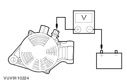
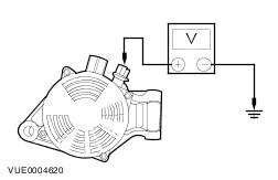
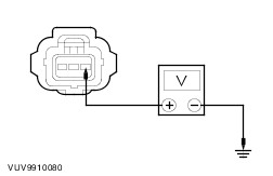
No | | A3: CHECK FOR A GOOD GROUND | | | 1 Ignition switch in position II. | | | 2 Measure the voltage between the generator housing and the battery negative terminal. | | | Is the voltage less than 0.5 volts? Yes No CLEAN and TIGHTEN the generator mounting, engine to body ground strap, and battery ground cable. TEST the system for normal operation. If the concern persists, INSTALL a new battery ground cable. | | A4: CHECK BATTERY CABLE | | | 1 Ignition switch in position II. | | | 2 Measure the voltage between the generator B+ terminal and the battery positive terminal. | | | Is the voltage less than 0.5 volts? Yes No CLEAN and TIGHTEN the battery positive cable connections. TEST the system for normal operation. | | A5: CHECK BATTERY FEED TO THE GENERATOR | | | 1 Measure the voltage between the generator B+ terminal, circuit 30-BA6 (RD), and ground. | | | Is the voltage equal to the battery voltage? Yes No REPAIR circuit 30-BA6 (RD) (starter motor to generator) or circuit 30-BB10 (RD) (battery to starter motor). TEST the system for normal operation. | | A6: CHECK POWER TO THE VOLTAGE REGULATOR | | | 1 Ignition switch in position 0. | | | 2 Disconnect Generator C870. | | | 3 Measure the voltage between the generator C870 pin 3, circuit 30-BA10 (RD), harness side and ground. | | | Is the voltage greater than 10 volts? Yes No REPAIR circuit 30-BA10. TEST the system for normal operation. | | A7: CHECK POWERTRAIN CONTROL MODULE AND COMMUNICATIONS LINK WITH GENERATOR | | | 1 Connect Generator C870. | | | 2 Connect the diagnostic tool. | | | 3 Ignition switch in position II. | | | 4 Retrieve PCM diagnostic trouble codes (DTCs). | | | Are any DTCs retrieved? Yes Use the WDS to diagnose the PCM and communications. No INSTALL a new generator.
REFER to: Generator - 1.6L Zetec-SE (Sigma)/1.4L (414-02 Generator and Regulator, Removal and Installation).
,
REFER to: Generator - 1.6L Zetec-E (Zetec)/1.8L/2.0L/2.0L Duratec-RS (Zetec) (414-02 Generator and Regulator, Removal and Installation) /
Generator - 1.8L Diesel (414-02 Generator and Regulator, Removal and Installation).
TEST the system for normal operation. | | PINPOINT TEST B : RADIO INTERFERENCE | | TEST CONDITIONS | DETAILS/RESULTS/ACTIONS | | B1: ISOLATE THE GENERATOR | | | 1 Remove the accessory drive belt.
REFER to: Accessory Drive Belt (303-05 Accessory Drive, Removal and Installation) /
Accessory Drive Belt - 1.8L Diesel (303-05 Accessory Drive, Removal and Installation) /
Accessory Drive Belt - Vehicles Built Up To: 03/2002, Vehicles Without: Accessory Drive Belt Tensioner (303-05 Accessory Drive, Removal and Installation) /
Accessory Drive Belt - Vehicles Built From: 03/2002, Vehicles Without: Accessory Drive Belt Tensioner (303-05 Accessory Drive, Removal and Installation).
| | | 2 Ignition switch in position II. | | | 3 Run the engine for a few seconds with the radio turned on. | | | Is interference still present? Yes Vehicles with subwoofer,
REFER to: Audio System (415-00 Information and Entertainment System - General Information, Diagnosis and Testing).
No CLEAN and TIGHTEN all mounting points and positive and ground cable connections. TEST the system for normal operation. If interference is still present, INSTALL a new generator.
REFER to: Generator - 1.6L Zetec-SE (Sigma)/1.4L (414-02 Generator and Regulator, Removal and Installation) /
Generator - 1.6L Zetec-E (Zetec)/1.8L/2.0L/2.0L Duratec-RS (Zetec) (414-02 Generator and Regulator, Removal and Installation) /
Generator - 1.8L Diesel (414-02 Generator and Regulator, Removal and Installation).
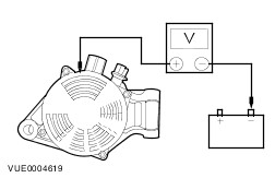
| Component Tests Generator On-Vehicle Tests - No-Load Test - Turn off all electrical loads and the ignition switch.
- Switch the multimeter to the voltage function.
- Connect the leads of the multimeter across the battery terminals.
- Read the voltage (base voltage).
- Run the engine at 1500 rpm with no electrical load.
- Read the voltage. The voltage should be in the range of 14.1 volts to 15.1 volts. If the voltage increase is less than 2.5 volts above the base voltage, carry out the Load Test. If the voltage increase is greater than 2.5 volts, REFER to the WDS.
Generator On-Vehicle Tests - Load Test - With the engine running, turn on the air conditioning (if equipped), turn the blower motor to high speed and the headlamps to high beam.
- Increase the engine speed to 2000 rpm. The voltage should increase a minimum of 0.5 volts above the base voltage. If the voltage does not increase as specified, REFER to the WDS. If the voltage increases as specified, the charging system is charging correctly. REFER to the Symptom Chart.
Battery Identification 1 - Cold crank amp (CCA) rating 2 - Reserve capacity (RC) rating (minutes) 6 - EN number (European Norm) 7 - Battery type: Ca = Silver/Calcium; Sb = Lead/Antimony Battery Surface Charge Removal Surface charge dissipation unit (SCD²) 1 - Connect black lead to battery - Connect red lead to battery + 2 - Red A indicator illuminates and green B indicator flashes 3 - Wait until green B indicator illuminates 4 - Disconnect from battery CAUTION:Prior to testing any battery, the surface discharge must be dissipated. This includes batteries that are returned disconnected from the vehicle. If the battery is holding a surface charge, the battery tester will give false readings. NOTE:The SCD² tool eliminates the need to dissipate the battery's surface charge via the manual process of loading the battery via the operation of the vehicles electrical systems. It also removes the variability in the process and makes sure that the actual dissipation of the surface charge is qualified prior to testing. - Connect the black lead to the battery negative terminal and the red lead to the battery positive terminal.
- The red indicator (A) illuminates and the green indicator (B) flashes.
- Wait until the green indicator (B) fully illuminates, then disconnect from the battery.
Alternative Method To Dissipate The Battery Surface Charge - Leave the battery to stand for a minimum of six hours without charging or discharging or remove the surface charge through partial loading as follows:
- Turn the ignition key to position II and switch on the headlamps (main beam), heated windshield (if equipped), heated rear window (if equipped) and the heater blower motor (position II). Leave the vehicle in this condition for a minimum of 60 seconds to dissipate the battery surface charge.
- Turn the ignition key to position 0 and switch off the headlamps, heated windshield (if equipped), heated rear window (if equipped) and the heater blower motor. Leave the vehicle in this condition for a minimum of five minutes before testing battery condition.
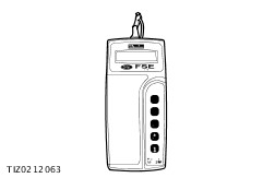
Battery Test NOTE:Using the Micro390 Battery Tester: To fully determine battery condition once the surface charge has been dissipated, the Micro390 battery tester must be used. For the Micro390 battery tester to operate, it requires a minimum of 5.5 volts charge to be present on the test battery. Therefore, if the Micro390 does not operate when connected to a test battery, then a charge of less than 5.5 volts is present. In this instance, the battery must be charged in line with the battery charging instructions prior to testing. In the event of a conflict of results between the charge eye indicator and the battery tester, the battery tester result must always be used. The charge eye indicator is for guidance only. - Connect the battery tester to the battery.
- Connect the red clip to the battery positive (+) terminal and the black clip to the battery negative (–) terminal.
-
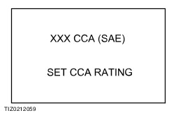
NOTE:The label affixed to the top of batteries progressively from 06/1998 identifies the battery CCA rating. Remove the battery if the label is obscured. Use the ”Arrow” buttons on the battery tester to scroll to the battery’s labelled CCA rating. - Press the ”Test” button that corresponds to the correct battery temperature.
- If the battery temperature is above zero degrees centigrade: press the ”sun” button. If the battery temperature is below zero degrees centigrade: press the ”Ice-crystal” button.
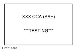
- Carry out the action based upon the test result displayed and the following table.
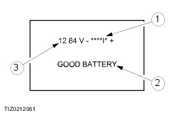
- Charge level bar graph.
- Test result.
- Battery voltage.
- Press the "information" button and carefully note the six-digit "Test Code" on the job card for claim submission and audit purposes (graphic shows an example of the code only).
Battery tester results and required actions | Tester Reading | Action | | GOOD BATTERY | Return to service | | GOOD RECHARGE | Fully charge the battery and return to service* | | CHARGE & RETEST | Fully charge the battery and retest | | REPLACE BATTERY or BAD CELL BATTERY | WARNING:Do not recharge the battery. Make sure that the surface charge was removed. If so, disconnect the battery from the vehicle and retest. If the result remains after surface charge removal, install a new battery. | | UNABLE TO TEST | Disconnect the battery from the vehicle and retest. | *In addition, it is advisable to check the vehicle electrical system. Check that the generator is functioning correctly and that all key-off loads (luggage compartment lamps, glove compartment lamp and interior lamps) are not staying on. |