| PINPOINT TEST A : THE REVERSING LAMPS ARE INOPERATIVE |
| TEST CONDITIONS | DETAILS/RESULTS/ACTIONS |
| A1: DETERMINE THE VEHICLE EQUIPMENT |
| | 1 Determine the vehicle equipment. |
| | Is the vehicle equipped with an automatic transmission? Yes No |
| A2: CHECK FUSE F53 (CJB) |
| | 1 Ignition switch in position 0. |
| | 2 CHECK Fuse F53 (CJB) (10 A). |
| | Is the fuse OK? Yes No INSTALL a new fuse F53 (10 A) and TEST the system for normal operation. If the fuse blows again, LOCATE and REPAIR the short to ground by using the wiring diagrams. TEST the system for normal operation. |
| A3: CHECK THE VOLTAGE AT FUSE F53 (CJB) |
| | 1 Connect Fuse F53 (CJB). |
| | 2 Ignition switch in position II. |
| | 3 Measure the voltage between fuse F53 (CJB) and ground. |
| | Is battery voltage indicated? Yes No REPAIR the open in the power supply of fuse F53 (CJB) by using the wiring diagrams. TEST the system for normal operation. If necessary CHECK the CJB and INSTALL a new one. TEST the system for normal operation. |
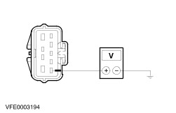
| A4: CHECK THE POWER SUPPLY OF THE TRANSMISSION SWITCH |
| | 1 Ignition switch in position 0. |
| | 2 Disconnect Transmission switch from connector C864. |
| | 3 Ignition switch in position II. |
| | 4 Measure the voltage between transmission switch, connector C864, Pin 2, circuit 15-LG28 (GN/WH), harness side and ground. |
| | Is battery voltage indicated? Yes No LOCATE and REPAIR the open in circuit 15-LG28(A) (GN/WH), between fuse F53 (CJB) and transmission switch, by using the wiring diagrams. TEST the system for normal operation. |
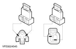
| A5: CHECK THE TRANSMISSION SWITCH |
| | 1 Ignition switch in position 0. |
| | 2 Connect a fused jumper wire (10 A) to the transmission switch, connector C864, between pin 2, circuit 15-LG28 (GN/WH), harness side and pin 1, circuit 15S-LG3 (GN/YE), harness side. |
| | 3 Ignition switch in position II. |
| | 4 Check the reversing lamp. |
| | Does the reversing lamp illuminate? Yes INSTALL a new transmission switch. TEST the system for normal operation. No - Reversing lamp is inoperative (wagon): GO to A10. - Reversing lamp is inoperative (4-door models): GO to A11. - Reversing lamp is inoperative (3-/5-door models): GO to A12. |
| A6: CHECK FUSE F40 (CJB) |
| | 1 Ignition switch in position 0. |
| | 2 CHECK Fuse F40 (CJB) (10 A). |
| | Is the fuse OK? Yes No INSTALL a new fuse F40 (10 A) and TEST the system for normal operation. If the fuse blows again, LOCATE and REPAIR the short to ground by using the wiring diagrams. TEST the system for normal operation. |
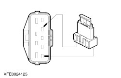
| A7: CHECK THE POWER SUPPLY OF THE TRANSMISSION RANGE SENSOR |
| | 1 Ignition switch in position 0. |
| | 2 Disconnect Transmission range sensor from connector C438. |
| | 3 Ignition switch in position II. |
| | 4 Measure the voltage between transmission range sensor, connector C438, Pin 1, circuit 15-TA18 (GN/OG), harness side and ground. |
| | Is battery voltage indicated? Yes No LOCATE and REPAIR the open in circuit 15-TA18 (GN/OG), between splice S54 and transmission range sensor, by using the wiring diagrams. TEST the system for normal operation. |
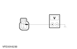
| A8: CHECK THE TRANSMISSION RANGE SENSOR |
NOTE:Do not remove the fused jumper wire if the reversing lamp is not illuminated in this teststep. |
| | 1 Ignition switch in position 0. |
| | 2 Connect Fuse F40 (CJB). |
| | 3 Connect a fused jumper wire (10 A) to the transmission range sensor, connector C438, between pin 1, circuit 15-TA18 (GN/OG), harness side and pin 4, circuit 15S-TA38 (GN/BU), harness side. |
| | 4 Ignition switch in position II. |
| | 5 Check the reversing lamp. |
| | Does the reversing lamp illuminate? Yes INSTALL a new transmission range sensor. TEST the system for normal operation. No |
| A9: CHECK THE VOLTAGE AT FUSE F40 (CJB) |
| | 1 Measure the voltage between F40 (CJB) and ground. |
| | Is battery voltage indicated? Yes - Reversing lamp is inoperative (wagon): GO to A10. - Reversing lamps are inoperative (4-door models): GO to A11. - Reversing lamp is inoperative (3-/5-door models): GO to A12. No LOCATE and REPAIR the open in the circuit(s), between transmission range sensor and fuse F40 (CJB), by using the wiring diagrams. TEST the system for normal operation. If necessary CHECK the CJB and INSTALL a new one. TEST the system for normal operation. |
| A10: CHECK THE POWER SUPPLY OF THE REAR LAMP ASSEMBLY (WAGON) |
| | 1 Ignition switch in position 0. |
| | 2 Connect Transmission switch with connector C864 (manual transmission only) . |
| | 3 Connect Transmission range sensor with connector C438 (automatic transmission only) . |
| | 4 Disconnect Rear lamp assembly from connector: . |
| | 5 Ignition switch in position II. |
| | 6 ENGAGE the reverse gear. |
| | 7 Measure the voltage between rear lamp assembly: - LHD: right-hand side, connector C475, pin 4, circuit 15S-LG9 (GN/BK), harness side and ground.
- RHD: left-hand side, connector C474, pin 4, circuit 15S-LD6 (GN/YE), harness side and ground.
|
| | Is battery voltage indicated? Yes LOCATE and REPAIR the open in circuit(s), between rear lamp assembly and ground G46, by using the wiring diagrams. TEST the system for normal operation. If necessary CHECK the rear lamp assembly and INSTALL a new one. TEST the system for normal operation. No - Vehicles with manual transmission: LOCATE and REPAIR the open in circuit(s), between transmission switch and rear lamp assembly, by using the wiring diagrams. TEST the system for normal operation. If necessary CHECK the rear lamp assembly and INSTALL a new one. TEST the system for normal operation. - Vehicles with automatic transmission: LOCATE and REPAIR the open in circuit(s), between fuse F40 (CJB) and rear lamp assembly, by using the wiring diagrams. TEST the system for normal operation. If necessary CHECK the rear lamp assembly and INSTALL a new one. TEST the system for normal operation. |
| A11: CHECK THE POWER SUPPLY OF THE REAR LAMP ASSEMBLY (4-DOOR MODELS) |
| | 1 Ignition switch in position 0. |
| | 2 Connect Transmission switch with connector C864 (manual transmission only). |
| | 3 Connect Transmission range sensor with connector C438 (automatic transmission only). |
| | 4 Disconnect Rear lamp assembly, left-hand side from connector C476. |
| | 5 Ignition switch in position II. |
| | 6 ENGAGE the reverse gear. |
| | 7 Measure the voltage between rear lamp assembly, left-hand side, connector C476, pin 4, circuit 15S-LG9A (GN/BK), harness side and ground. |
| | Is battery voltage indicated? Yes LOCATE and REPAIR the open in circuit 31-DA18 (BK), between splice S184 and ground G46, by using the wiring diagrams. TEST the system for normal operation. No - Vehicles with manual transmission: LOCATE and REPAIR the open in circuit(s), between transmission switch and splice S211, by using the wiring diagrams. TEST the system for normal operation. If necessary CHECK the rear lamp assembly and INSTALL a new one. TEST the system for normal operation. - Vehicles with automatic transmission: LOCATE and REPAIR the open in circuit(s), between fuse F40 (CJB) and splice S211, by using the wiring diagrams. TEST the system for normal operation. If necessary CHECK the rear lamp assembly and INSTALL a new one. TEST the system for normal operation. |
| A12: CHECK THE POWER SUPPLY OF THE REVERSING LAMP (3/5- DOOR MODELS) |
| | 1 Ignition switch in position 0. |
| | 2 Connect Transmission switch with connector C864 (manual transmission only). |
| | 3 Connect Transmission range sensor with connector C438 (automatic transmission only). |
| | 4 Disconnect Reversing lamp from connector:. |
| | 5 Ignition switch in position II. |
| | 6 ENGAGE the reverse gear. |
| | 7 Measure the voltage between reversing lamp: - LHD: right-hand side, connector C430, pin 1, circuit 15S-LG9 (GN/BK), harness side and ground.
- RHD: left-hand side, connector C434, pin 1, circuit 15S-LD6 (GN/YE), harness side and ground.
|
| | Is battery voltage indicated? Yes LOCATE and REPAIR the open in circuit(s), between reversing lamp and ground G46, by using the wiring diagrams. TEST the system for normal operation. If necessary CHECK the reversing lamp and INSTALL a new one. TEST the system for normal operation. No - Vehicles with manual transmission: LOCATE and REPAIR the open in circuit(s), between transmission switch and reversing lamp, by using the wiring diagrams. TEST the system for normal operation. If necessary CHECK the reversing lamp and INSTALL a new one. TEST the system for normal operation. - Vehicles with automatic transmission: LOCATE and REPAIR the open in circuit(s), between fuse F40 (CJB) and reversing lamp, by using the wiring diagrams. TEST the system for normal operation. If necessary CHECK the reversing lamp and INSTALL a new one. TEST the system for normal operation. |