| Removal and Installation Removal WARNING:To avoid accidental deployment, the air bag control module backup power supply must be depleted. Wait at least one minute after disconnecting the battery ground cable(s) before commencing any repair or adjustment to the supplemental restraint system (SRS), or any component(s) adjacent to the SRS sensors. Failure to follow these instructions may result in personal injury. WARNING:To minimize the possibility of premature deployment, do not use radio key code savers when working on the supplemental restraint system. Failure to follow this instruction may result in personal injury. WARNING:Never probe the electrical connectors of air bag modules or any other supplemental restraint system component. Failure to follow this instruction may result in personal injury. CAUTION:Make sure the road wheels are in the straight ahead position. CAUTION:A new clockspring is supplied pre-centralized and sealed with a red sealing key. If a new clockspring is installed break-off the red sealing key. If an existing clockspring is being installed, carry out the centralizing procedure. | | -
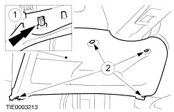
Detach the instrument panel lower panel from the instrument panel. - Remove the retaining screws.
- Release the clip.
| | | -
Detach the steering column upper shroud from the steering column lower shroud. - Using a thin bladed screwdriver, release the two clips (one each side).
| | | -
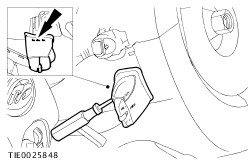
Detach the audio control switch from the steering column lower shroud (if equipped). - Using a thin bladed screwdriver, release the locking tang.
| | | -
Remove the audio control switch (if equipped). - Disconnect the electrical connector.
| | | -
Remove the steering column lower shroud. - Release the steering column locking lever.
- Remove the retaining screws.
| | | -
Detach the multifunction switches from the clockspring and position them to one side. - Depress the locking tang in turn and slide each switch upwards.
| | | -
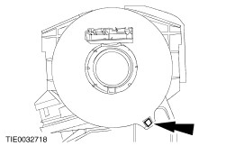
Disconnect the clockspring electrical connector. - Using a thin bladed screwdriver, release the locking tang.
| | | -
CAUTION:Note the position of the spacing collar within the center of the clockspring. Remove the clockspring. - Release the locking tangs from the steering column.
| Installation All vehicles WARNING:Never probe the electrical connectors of air bag modules or any other supplemental restraint system component. Failure to follow this instruction may result in personal injury. | | -
Install the clockspring. - Make sure the retaining tangs lock into position on the steering column.
| | | -
NOTE:An audible click will be heard when the locking tangs are fully engaged. Connect the clockspring electrical connector. | | | -
NOTE:An audible click will be heard when the locking tangs are fully engaged. Attach the multifunction switches to the clockspring. | | | -
Install the steering column lower shroud. - Install the screws.
- Lock the steering column locking lever.
| | | -
NOTE:An audible click will be heard when the locking tangs are fully engaged. Install the audio control switch (if equipped). - Connect the audio control switch electrical connector.
- Install the audio control switch.
| | | -
Install the steering column upper shroud. | | | -
Attach the instrument panel lower panel to the instrument panel. - Secure the clip.
- Install the screws.
| | | -
CAUTION:Do not rotate the new clockspring between breaking the red sealing key and installing the steering wheel. If the vehicle is left unattended by the technician between breaking the red seal and installing the steering wheel, carry out the centralizing procedure. Break the red sealing key, if necessary. | | | -
WARNING:Incorrect centralization may result in premature component failure. If in doubt when centralizing the clockspring, repeat the centralizing procedure. Failure to follow this instruction may result in personal injury. CAUTION:Make sure the road wheels are in the straight ahead position. Centralize the clockspring. - Turn the clockspring in a counterclockwise direction until resistance is felt.
- Turn the clockspring in a clockwise direction, until the arrow marked on the rotor of the clockspring aligns with the raised 'V' section at the 12 o'clock position on the outer cover of the clockspring (approximately two and one half turns).
| | | -
CAUTION:Make sure the spacing collar is correctly located when installing the steering wheel. Do not install the steering wheel if the collar is missing. Install the spacing collar. | | | -
CAUTION:If there is any break between centralizing the clockspring and installing the steering wheel, or the vehicle is left unattended by the technician, the centralizing procedure MUST be repeated. | Vehicles with stability assist | | -
WARNING:The electronic stability program must be re-configured. Failure to follow this instruction may result in personal injury. Configure the electronic stability program using WDS. | |