| Removal and Installation Special Tool(s) | | Alignment Pins, Subframe 205-316 (15-097A) | | | Separator, Ball Joint 211-020 (13-006) | General Equipment Transmission jack 5 mm Allen key Removal All vehicles | | -
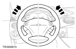
NOTE:Make sure the road wheels are in the straight ahead position. Centralize the steering and lock it in position. | Vehicles built up to 12/1998 | | -
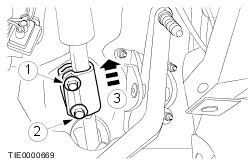
Disconnect the steering column shaft from the steering gear pinion extension. - Loosen the upper retaining bolt.
- Remove the lower retaining bolt.
- Push the sleeve up.
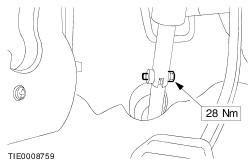
| Vehicles built 12/1998 onwards | | -
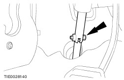
Disconnect the steering column shaft from the steering gear pinion extension. | All vehicles | | -
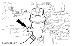
Drain the power steering fluid. - Allow the fluid to drain into a suitable container.
| | | -
Remove the front wheels and tires.
For additional information, refer to: Wheel and Tire (204-04 Wheels and Tires, Removal and Installation).
| | | -
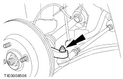
CAUTION:Leave the tie-rod end retaining nuts in place to protect the ball joint studs. Loosen the tie-rod end retaining nut on both sides. | | | -
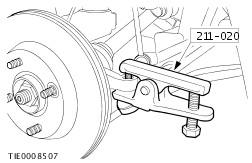
CAUTION:Using a soft cloth, protect the ball joint seal to prevent damage. Using the special tool, detach the tie-rod end from the wheel knuckle on both sides. - Remove and discard the tie-rod end retaining nuts.
| | | -
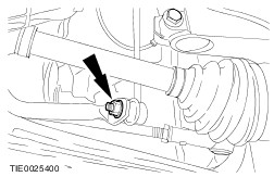
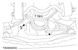
NOTE:Using a 5 mm Allen Key, prevent the ball joint from rotating. Detach the stabilizer bar connecting link from the stabilizer bar on both sides. | | | -
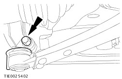
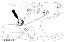
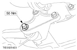
CAUTION:Using a soft cloth, protect the ball joint seal to prevent damage. Detach the lower arm ball joint from the wheel knuckle on both sides. | | | -
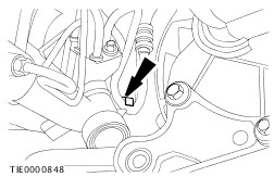
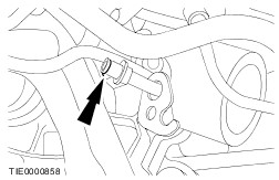
Remove the engine support insulator to transaxle center retaining bolt. | | | -
Remove the steering gear heat shield (two bolts). | | | -
Detach the power steering line from the clamp. | | | -
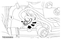
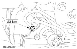
Detach the power steering line from the power steering gear. - Remove the retaining bolt.
- Rotate the power steering line clamp clockwise.
- Allow the oil to drain into a suitable container.
| | | -
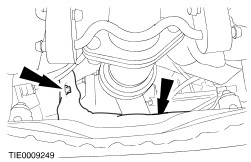
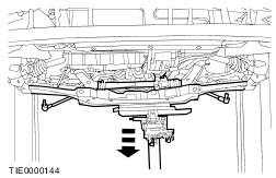
Remove the crossmember retaining bolts (support removed for clarity). | Installation All vehicles | | -
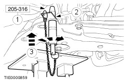
CAUTION:Make sure the crossmember ball bearing washers are installed correctly. Using a suitable transmission jack and the special tool, position and align the crossmember. - Insert the alignment pins through the crossmember alignment holes and the washers.
- Slide the locking plates on top of the washers and into the groove of the tool and tighten the alignment pin sleeve
- Raise the crossmember engaging the alignment pins into the chassis aligning holes.
| | | -
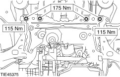
CAUTION:While tightening the crossmember retaining bolts, make sure the crossmember does not move. Install the crossmember retaining bolts (support removed for clarity). | | | -
Remove the crossmember alignment pins. | | | -
NOTE:Check the O-ring seals for perishing, splits or cuts. Install new O-ring seals as necessary. | | | -
Attach the power steering lines to the power steering gear. - Rotate the power steering line clamp counterclockwise.
| | | -
Attach the power steering line to the clamp. | | | -
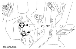
Install the steering gear heat shield (two bolts). | | | -
Install the engine support insulator to transaxle center retaining bolt. | | | -
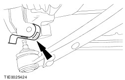
CAUTION:Make sure the heat shield is installed to prevent damage to the ball joint. Install the heat shield on both sides. | | | -
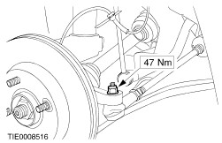
Attach the lower arm ball joint to the wheel knuckle on both sides. | | | -
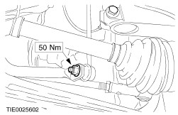
NOTE:Using a 5 mm Allen key, prevent the ball joint from rotating. Attach the stabilizer bar connecting link to the stabilizer bar on both sides. | | | -
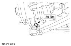
NOTE:Install new retaining nuts. Attach the tie-rod ends to the wheel knuckle on both sides. | | | -
Install the front wheels and tires.
For additional information, refer to: Wheel and Tire (204-04 Wheels and Tires, Removal and Installation).
| Vehicles built up to 12/1998 | | -
CAUTION:Make sure the road wheels are in straight ahead position. Connect the steering column shaft to the steering gear pinion extension. | Vehicles built 12/1998 onwards | | -
WARNING:Install a new retaining bolt. Failure to follow these instructions may result in personal injury. CAUTION:Make sure the road wheels are in straight ahead position. Connect the steering column shaft to the steering gear pinion extension. | All vehicles | | -
Fill and bleed the power steering system.
For additional information, refer to: Power Steering System Filling (211-00 Steering System - General Information, General Procedures) /
Power Steering System Bleeding (211-00 Steering System - General Information, General Procedures).
| |