This manual has been written in a format that is designed to meet the needs of technicians worldwide. The objective is to use common formats and include similar content in each manual.
This manual provides general descriptions for accomplishing diagnosis and testing, service and repair work with tested, effective techniques. Following them will help assure reliability.
The special tool(s) table provided at the beginning of each procedure shows all special tools required to carry out a repair. Where possible, illustrations are provided to assist in identifying the special tool required.
Appropriate service methods and correct repair procedures are essential for the safe, reliable operation of all motor vehicles as well as the personal safety of the individual carrying out the work.
This manual cannot possibly anticipate all such variations and provide advice or cautions as to each. Anyone who departs from the instructions provided in this manual must first establish that he compromises neither his personal safety nor the vehicle integrity by his choice of methods, tools or components.
As you read through this manual, you will come across WARNINGS, CAUTIONS and NOTES.
A warning, caution or note is placed at the beginning of a series of steps if it applies to multiple steps. If the warning, caution or note only applies to one step, it is placed at the beginning of the specific step (after the step number).
Overview procedures contain an exploded view illustration(s). The numbered sequence within the illustration(s) indicate the order to be followed when removing/disassembling or when installing/assembling a component. Additional information, symbol(s) or a torque figure, may also be shown alongside the component.
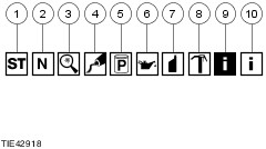
There are ten symbols used to give additional information when removing/disassembling or when installing/assembling a component.
Any requirement for special tools will picture the tool, showing it in use and with its tool number shown. Torque settings will be given at the relevant point in the procedure.
Trustmark Authoring Standards (TAS) Removal and Installation Procedures
NOTE:TAS style procedures can be identified by steps that have no accompanying step text and the magenta color of the electrical connectors and fasteners such as nuts, bolts, clamps or clips.
A TAS removal and installation procedure uses a sequence of color illustrations to indicate the order to be followed when removing/disassembling or installing/assembling a component.
Many of the TAS procedures will have the installation information within the removal steps. These procedures will have the following note at the beginning of the procedure:
NOTE:Removal steps in this procedure may contain installation details.
Items such as O-ring seals, gaskets, seals, self-locking nuts and bolts are to be discarded and new components installed unless otherwise stated within the procedure. Coated nuts or bolts are to be reused, unless damaged or otherwise stated within the procedure.
Specification procedures will contain all technical data that are not part of a repair procedure.
TAS Graphics
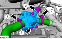
Colors used in the graphic are as follows:
- Blue - Indicates the target item, item to be removed/installed or disassembled/assembled
- Green and Brown - Indicates a secondary item that needs to be detached, removed/installed or disassembled/assembled prior to the target item
- Magenta - Indicates electrical connectors and fasteners such as nuts, bolts, clamps or clips
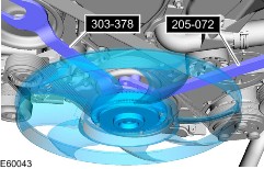
- Pale Blue - is for the special tool(s) and general equipment
There may be multiple steps assigned to one illustration.
Numbered pointers are used to indicate the number of electrical connectors and fasteners such as nuts, bolts, clamps or clips.
Items in the illustration can be transparent or use cutouts to show hidden detail(s).
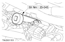
Special Tools and Torque Figure(s)
Special tools will be shown with the tool number in the illustration. The special tool number(s), general equipment, material(s) and torque figure(s) used for the procedure step will be shown in the text column.
How to Use This Manual
This manual covers diagnosis and testing, service and repair procedures.
This manual is structured into groups and sections, with specific system sections collected together under their relevant group.
A group covers a specific portion of the vehicle. The manual is divided into five groups, General Information, Chassis, Powertrain, Electrical and Body and Paint. The number of the group is the first number of a section number.
Pages at the start of the manual list all sections available. Each section has a contents list detailing Specifications, Description and Operation, Diagnosis and Testing, In Vehicle Repairs, Disassembly and Assembly, Removal and Installation.
If components need to be removed or disassembled in sequence, the sequence will be identified numerically in a graphic and the corresponding text will be numbered accordingly.
All left and right-hand references to the vehicle are taken from a position sitting in the driver seat looking forward.
All left and right-hand references to the engine are taken from a position at the flywheel looking towards the front camshaft pulley.
Where appropriate, instructions will be given for the use of the diagnostic tool.
Inspection and Verification
Visual Inspection Charts, Symptom Charts and other information charts (such as diagnostic routines) or supplement test procedures with technical specifications will navigate the user to a specific test procedure.
Symptom Chart
The symptom chart indicates symptoms, sources and actions to address a condition.
Pinpoint Tests
For electrical systems, pinpoint test steps are used to identify the source of a concern in a logical, step-by-step manner. pinpoint tests have two columns: CONDITIONS and DETAILS/RESULTS/ACTIONS.
The CONDITIONS column is used exclusively for graphics and icons (with or without captions) and the DETAILS/RESULTS/ACTIONS column provides direction to another test step or specific corrective actions.
The boxed numbers indicate the order in which the described action is to be performed.
Component Tests
A component test is used when a component is tested in multiple pinpoint tests, or if a procedure is too complicated to be formatted within a single page of the pinpoint test.
Graphics
Test graphics show the measurement or test to be performed in a test step.
A representative tester graphic is used for voltmeters and ohmmeters.
If multiple measurements are made in a single graphic, the test leads are drawn with a solid line until the test lead splits to indicate the multiple measurements, at which point dashed lines are used.
Breakout box-type testers are represented by a double circle test pin. Test pins are labeled with the pin number.