| Diagnosis and Testing Refer to Wiring Diagrams Section 413-01, for schematic and connector information. Worldwide Diagnostic System (WDS) Inspection and Verification - Verify the customer concern.
- Visually inspect for obvious signs of mechanical or electrical damage.
Visual Inspection Chart | Mechanical | Electrical | - Engine oil filter
- Engine oil level
- Engine coolant level
- Oil pressure switch
- Engine coolant level
- Coolant thermostat
- Engine coolant temperature (ECT) sensor
- Fuel gauge
- Collapsed or damaged fuel tank
- Recirculation hose
- Fuel tank filler pipe/hose
- Indicated fuel level
- Fuel lines
- Fuel tank filler cap
- Fuel filter (external to the fuel tank)
- Fuel tank
- Door adjustment
| - Fuse(s)
- Wiring harness
- Electrical connector(s)
- Instrument cluster
- Light emitting diode(s) (LED)(s)
| - If an obvious cause for an observed or reported concern is found, correct the cause (if possible) before proceeding to the next step.
-
NOTE:If none of the following warning indicators are operating correctly this may indicate a concern with the central junction box (CJB). If only one or two of the following warning indicators are not operating correctly this may indicate an instrument cluster concern. Verify the following warning indicators are working correctly: - Charging.
- Turn signals.
- Headlamps.
- If the cause is not visually evident, verify the symptom and enter the instrument cluster Self-Diagnostic Mode.
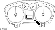
Self-Diagnostic Mode. Vehicles with low series instrument cluster NOTE:The instrument cluster tripmeter reset button is located on the right-hand side of the instrument cluster lens. - To enter the instrument cluster Self-Diagnostic Mode. Simultaneously press and hold the tripmeter RESET button and turn the ignition switch from position 0, to position II.
- Entry to the Self-Diagnostic Mode is confirmed when 'tESt' is displayed in the odometer tripmeter liquid crystal display (LCD). The tripmeter reset button must be released within three seconds of 'tESt' being displayed or the instrument cluster will exit the Self-Diagnostic mode.
- To navigate through or skip any of the instrument cluster Self-Diagnostic Mode tests, press the tripmeter RESET button. If the reset button is depressed for more than 3 seconds between tests, the instrument cluster will exit the Self-Diagnostic Mode.
- The Self-Diagnostic Mode is deactivated when the ignition switch is turned to the OFF position or low battery voltage is detected.
- If input data to the instrument cluster is missing or invalid, the tripmeter LCD will display '----'
- If the Self-Diagnostic Mode cannot be accessed, use the WDS to diagnose the instrument cluster.
NOTE:Additional tests are available after the following Self-Diagnostic Mode tests, but are not applicable for this diagnostic. | Test | Odometer Display | Gauge/Indicator/Display Tested | Description | | 1. Self-Diagnostic entry | tESt | Instrument cluster | Establishes Self-Diagnostic Mode. | | 2. Gauge sweep | gAgE | Tachometer, speedometer, temperature and fuel | All gauges go through a full up and down pointer sweep smoothness check. The pointers should take 3 seconds to achieve full sweep and 3 seconds to return to the rest position. | | 3. Odometer LCD | 888888 | Odometer LCD | Fills in the LCDs of the odometer display. | | 4. Indicator LED(s) | LeD | Indicators and warning indicators | Illuminates all the LED warning indicators that are controlled by the instrument cluster. | | 5. ROM level | r XXXX / FAIL | Instrument cluster read only memory (ROM) | Displays the instrument cluster ROM level and type. | | 6. Not required | ErXXXX | - | Not required. | | 7. Not required | E XX / FAIL | - | Not required. | | 8. Manufacturing date | dtXXXX | Instrument cluster manufacturing date | Displays the instrument cluster date of manufacture. | | 9. Diagnostic trouble code (DTC) | | DTCs | Display the individual DTCs at 1 second intervals. REFER to the WDS to diagnose the instrument cluster. | | 10. Vehicle speed mph | SPXXXX | Speedometer | Displays the speed signal input in miles per hour. | | 11. Vehicle speed km/h | SPXXXX | Speedometer | Displays the speed signal input in kilometers per hour. | | 12. Not required | SgXXXX | - | Not required. | | 13. Engine speed | tAXXXX | Tachometer | Displays the engine speed input signal (RPM) | | 14. Not required | tgXXXX | - | Not required. | | 15. Odometer count | od XXX | Odometer | Displays the odometer rolling count | | 16. Fuel volume | F XXX | Fuel sender system | - Displays the fuel volume signal input.
- 000 - 009 Short circuit
- 010 - 254 Normal range
- 255 open circuit
| | 17. Not required | FgXXXX | - | Not required. | | 18. Not required | FL XX | - | Not required. | | 19. Fuel level percentage | FP XX | Fuel gauge | - Displays the fuel average percentage level.
- Range of display 00 to 64
- 64 being 100% full
- FF will be displayed for invalid data
| | 20. Engine coolant temperature (ETC) | XXX C | ECT | - Displays the engine coolant temperature as a decimal.
- Range 0 to 254
- 255 would indicate invalid data
| | 21. Not required | XXX Cg | - | Not required. | | 22. Battery voltage | btXXX | Battery voltage | Displays battery voltage input. | | 23. to 28. Not required | A0-XX to A5-XX | - | Not required. | | 29. to 42. Not required | PA-HH to Pn-HH | - | Not required. | | 43. to 46. Not required | P1 XX to P4 XX | - | Not required. | | 47. Distance to empty | dtEXXX | Trip computer | Displays the distance to fuel tank empty. | | 48. Fuel economy | rAFEXX | Trip computer | Displays the rolling average fuel economy in miles per UK gallon. | Self-Diagnostic Mode. Vehicles with mid or high series instrument cluster NOTE:The set button is located on the steering column left hand multifunction switch. - To enter the instrument cluster Self-Diagnostic Mode. Simultaneously press and hold the SET button and turn the ignition switch from position 0, to position II.
- Entry to the Self-Diagnostic Mode is confirmed when 'TEST' is displayed in the odometer tripmeter liquid crystal display (LCD). The tripmeter set button must be released within three seconds of 'TEST' being displayed or the instrument cluster will exit the Self-Diagnostic Mode.
- To navigate through or skip any of the instrument cluster Self-Diagnostic Mode tests, press the SET button. If the set button is depressed for more than 3 seconds between tests, the instrument cluster will exit the Self-Diagnostic Mode.
- The Self-Diagnostic Mode is deactivated when the ignition switch is turned to the OFF position or low battery voltage is detected.
- If input data to the instrument cluster is missing or invalid, the tripmeter LCD will display '----'
- If the Self-Diagnostic Mode cannot be accessed, use the WDS to diagnose the instrument cluster.
NOTE:Additional tests are available after the following Self-Diagnostic Mode tests, but are not applicable for this diagnostic. Self-Diagnostic Mode | Test | Odometer Display | Gauge/Indicator/Display Tested | Description | | 1. Self-Diagnostic entry | | Instrument cluster | Establishes Self-Diagnostic Mode. | | 2. Gauge sweep | | Tachometer, speedometer, temperature and fuel | All gauges go through a full up and down pointer sweep smoothness check. The pointers should take 3 seconds to achieve full sweep and 3 seconds to return to the rest position. | | 3. Odometer LCD | Filled in black | Odometer LCD | Fills in the LCDs of the odometer display. | | 4. Indicator LED(s) | | Indicators and warning indicators | Illuminates all the LED warning indicators that are controlled by the instrument cluster. | | 5. ROM level | | Instrument cluster read only memory (ROM) | Displays the instrument cluster ROM level and type. | | 6. Not required | | - | Not required. | | 7. Not required | - NVM EEPROM LVL
- XXXX / FAIL
| - | Not required. | | 8. Manufacturing date | | Instrument cluster manufacturing date | Displays the instrument cluster date of manufacture. | | 9. Diagnostic trouble code (DTC) | | DTCs | Display the individual DTCs at 1 second intervals. REFER to the WDS to diagnose the instrument cluster. | | 10. Vehicle speed mph | | Speedometer | Displays the speed signal input in miles per hour. | | 11. Vehicle speed km/h | | Speedometer | Displays the speed signal input in kilometers per hour. | | 12. Not required | | - | Not required. | | 13. Engine speed | | Tachometer | Displays the engine speed input signal (RPM) | | 14. Not required | | - | Not required. | | 15. Odometer count | | Odometer | Displays the odometer rolling count | | 16. Fuel volume | | Fuel sender system | - Displays the fuel volume signal input.
- 000 - 009 Short circuit
- 010 - 254 Normal range
- 255 open circuit
| | 17. Not required | | - | Not required. | | 18. Not required | | - | Not required. | | 19. Fuel level percentage | | Fuel gauge | - Displays the fuel average percentage level.
- Range of display 00 to 64
- 64 being 100% full
- FF will be displayed for invalid data
| | 20. Engine coolant temperature (ECT) | | ECT | - Displays the engine coolant temperature as a decimal.
- Range 0 to 254
- 255 would indicate invalid data
| | 21. Not required | | - | Not required. | | 22. Battery voltage | | Battery voltage | Displays battery voltage input. | | 23. to 28. Not required | - A/D INPUT 00 to A/D INPUT 05
- XX
| - | Not required. | | 29. to 42. Not required | | - | Not required. | | 43. to 46. Not required | - PERSONALITY 01 to PERSONALITY 04
- XX
| - | Not required. | | 47. Distance to empty | | Information and message center | Displays the distance to fuel tank empty. | | 48. Fuel economy | | Information and message center | Displays the rolling average fuel economy in miles per UK gallon. | Instrument Cluster DTC Index Chart | Self Diagnostic Mode Displayed DTC | DTC | Description | Source | Action | | 115A | P115A | Low Fuel Level - Forced Limited Power | Instrument cluster | - If the fuel gauge shows EMPTY and the Distance To Empty = 0 kilometers/miles: Delete the DTC and the customer can refill the fuel tank. NO further action must be taken.
- If the fuel gauge shows more than EMPTY and/or the Distance To Empty is greater than 0 kilometers/miles GO to Pinpoint Test F.
| | 115B | P115B | Low Fuel Level - Forced Engine Shutdown | Instrument cluster | - If the fuel gauge shows EMPTY and the Distance To Empty = 0: Delete the DTC and the customer can refill the fuel tank. NO further action must be taken.
- If the fuel gauge shows more than Empty and/or the Distance To Empty is greater than 0 kilometers/miles GO to Pinpoint Test F.
| | 9202 | B1202 | Fuel pump and sender unit/fuel level sensor open circuit | Instrument cluster | GO to Pinpoint Test A. | | 9204 | B1204 | Fuel pump and sender unit/fuel level sensor short to ground | Instrument cluster | GO to Pinpoint Test A. | | 9317 | B1317 | Battery voltage high (greater than 16V) | Instrument cluster | REFER to the WDS | | 9318 | B1318 | Battery voltage low (less than 10V) | Instrument cluster | REFER to the WDS | | 9342 | B1342 | PCM is defective | Instrument cluster | REFER to the WDS | | A477 | B2477 | Module configuration failure | Instrument cluster | REFER to the WDS | | E196 | U2196 | Invalid data for engine RPM (Invalid CAN message) | Instrument cluster | REFER to the WDS | | E197 | U2197 | Invalid data for vehicle speed (Invalid CAN message) | Instrument cluster | REFER to the WDS | | E198 | U2198 | Invalid data for fuel pulse (Invalid CAN message) | Instrument cluster | REFER to the WDS | | E199 | U2199 | Invalid data for engine coolant temperature (Invalid CAN message) | Instrument cluster | REFER to the WDS | | E200 | U2200 | Invalid data for odometer (Invalid CAN message) | Instrument cluster | REFER to the WDS | | E201 | U2201 | Invalid data for ambient temperature (Invalid CAN message) | Instrument cluster | REFER to the WDS | - The self-diagnostic mode is to act as a guide to establish if the concern is instrument cluster related. For any concerns not related to the fuel gauge, REFER to the WDS to continue diagnostics.
- For any fuel gauge concerns, REFER to the Symptom Chart.
Symptom Chart | Symptom | Possible Sources | Action | | The fuel gauge pointer does not move down at a constant rate (Full to 3/4 and 1/4 to empty periods vary) | * The fuel gauge considers unindicated full and empty reserve as part of the indicated volume. The pointer catches up with the real volume outside of these areas. | * No action required. Do not install a new component. | | Information and message center inconsistent with the fuel gauge | * The fuel gauge considers unindicated full and empty reserve as part of the indicated volume. The pointer catches up with the real volume outside of these areas. * A certain amount of fuel is not indicated or not useable respectively and is needed to avoid unintended engine hesitations at low fuel levels. This amount is carline and engine type dependent. | * No action required. Do not install a new component. | | The low fuel warning indicator illuminates too early | * This is dependant on the drive style. The on-board computer calculates the average consumption and illuminates the low fuel warning indicator when there is 80 Km (50 miles) of fuel left in the fuel tank. The on-board computer does not consider a more economical drive style after a higher fuel consumption, but keeps the Distance To Empty (DTE) constant until the fuel level has caught up with the remaining DTE. | * No action required. Do not install a new component. | | The fuel gauge pointer moves too quickly off the full position or needs too long to move off the full position after refuelling | * A certain amount of unindicated fuel is normal and is dependent on fuel tank geometry and the fuel station filler nozzle shutoff behaviour | * No action required. Do not install a new component. | | Indicated fuel level does not match the amount of fuel expected to be in the fuel tank | * A certain amount of fuel is not indicated or not useable respectively and is needed to avoid unintended engine hesitations at low fuel levels. This amount is carline and engine type dependent. | * No action required. Do not install a new component. | | Indicated fuel level does not match the amount of fuel expected to be in the fuel tank | * A certain amount of fuel is not indicated or not useable respectively and is needed to avoid unintended engine hesitations at low fuel levels. This amount is carline and engine type dependent. | * No action required. Do not install a new component. | | Fuel gauge shows less than full (even when refilled/trickle filled) | * Fuel tank refilled with the ignition ON | * Refilling with the ignition OFF next time will cure the concern. Do not install a new component. | | * Fuel tank only filled up to the 1st click on the fuel station filling nozzle. | * Advise the customer to fill the fuel tank up to the 3rd click on the fuel station filling nozzle. Do not install a new component. | | * Superseded ROM level in the instrument cluster * Fuel gauge pointer sticking at times or does not move over the complete range * Instrument cluster not receiving or processing input signals correctly * Recirculation hose incorrectly routed * Float arm obstructed or collision between the fuel fired booster heater pipe (if equipped) and the float arm * Fuel tank does not reach correct fuel level * Fuel level resistor card | * | | Fuel gauge shows empty even when refilled | * Fuel gauge pointer sticking at times or does not move over the complete range * Open circuit * Short circuit * Instrument cluster not receiving or processing input signals correctly * Float arm obstructed or collision between the fuel fired booster heater pipe (if equipped) and the float arm | * | | Fuel gauge shows 1/4, ½ or is stuck at a specific position | * Fuel gauge pointer sticking at times or does not move over the complete range * Float arm obstructed or collision between the fuel fired booster heater pipe (if equipped) and the float arm | * | | Fuel gauge pointer delayed in moving up when the fuel tank is refilled | * Fuel tank refilled with the ignition ON | * Refilling with the ignition OFF next time will cure the concern. Do not install a new component. | | * Fuel gauge pointer sticking at times or does not move over the complete range * Float arm obstructed or collision between the fuel fired booster heater pipe (if equipped) and the float arm | * | | Fuel gauge pointer fluctuates up and down while driving on straight/flat roads | * Fuel gauge pointer sticking at times or does not move over the complete range * Float arm obstructed or collision between the fuel fired booster heater pipe (if equipped) and the float arm | * | Pinpoint Tests NOTE:Use a digital multimeter for all electrical measurements. | PINPOINT TEST A : FUEL GAUGE SHOWS LESS THAN FULL (EVEN WHEN REFILLED/TRICKLE FILLED) | | TEST CONDITIONS | DETAILS/RESULTS/ACTIONS | | A1: CHECK THE INSTRUMENT CLUSTER ROM LEVEL (HIGH SERIES INSTRUMENT CLUSTER ONLY) | | | 1 Carry out the instrument cluster Self-Diagnostic Mode and scroll to the ROM LEVEL | | | Is the ROM LEVEL 040D, 0422, 0423 or 0424? Yes REFER to the WDS. SELECT Toolbox/Module Programming/Module Reprogramming/HEC. FLASH the instrument cluster with ROM LEVEL 0425 or later. Test the system for normal operation. No | | A2: CHECK THE OPERATION OF THE FUEL GAUGE POINTER | | | NOTE:The fuel gauge pointer should move smoothly from empty to full in 2.5 seconds. At the maximum full position, the fuel gauge pointer must be on the full mark and not below it. 1 Carry out the instrument cluster Self-Diagnostic Mode. | | | Does the fuel gauge pointer operate correctly? Yes No REFER to the WDS. SELECT Guided Diagnostic/Body/Instrument Panel and Console/Instrument Cluster/Fuel Gauge and follow the instructions on the display. | | A3: CHECK THE INSTRUMENT CLUSTER IS RECEIVING AND PROCESSING INPUT SIGNALS CORRECTLY | | | 1 With the vehicle on level ground, fill the fuel tank up to the 1st click on the fuel station filler nozzle, making sure that at least 10 liters of fuel is added (with the ignition switch OFF). | | | 2 Make sure that the fuel gauge pointer is on the FULL mark. | | | 3 Carry out the instrument cluster Self-Diagnostic Mode and scroll to the FUEL A/D and the FUEL PERCENT tests and note the readings. | | | Is the FUEL A/D less than or equal to 17 with the pointer showing FULL?Is the FUEL PERCENT greater than or equal to 5F, 60, 61, 62, 63, 64 with the pointer showing FULL? Yes Suspect fuel tank not filled correctly previously. Re-verify the customer concern. No | | A4: CHECK THE FUEL GAUGE WIRING | | | 1 Remove the instrument cluster.
REFER to: Instrument Cluster (413-01 Instrument Cluster, Removal and Installation).
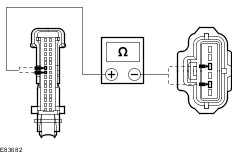
| | | 2 Measure the resistance between the instrument cluster C809 pin 8, circuit 8-GA7 (WH/RD), harness side and pin 7, circuit 9-GA7 (BN/RD), harness side. | | | Is the resistance less than 13.5 Ohms? Yes REFER to the WDS. SELECT Guided Diagnostic/Body/Instrument Panel and Console/Instrument Cluster/Fuel Gauge and follow the instructions on the display. No | | A5: CHECK THAT THE FUEL REACHES THE CORRECT FILL LEVEL | | | NOTE:Make a note of the amount of fuel required to reach the 3rd click on the fuel station filler nozzle. 1 Fill the fuel tank up to the 3rd click on the fuel station filler nozzle. | | | Does the fuel gauge pointer show FULL with more than 3 liters of fuel added? Yes No If the amount of fuel added is less than 3 liters, the customer may have refuelled at a fuel station with a too high fill rate. Advise customer to fill up to the 3rd click on the fuel station filler nozzle. Do not install a new component.If the fuel gauge pointer still shows less than FULL, Vehicles with fuel fired booster heater GO to A7. Vehicles without fuel fired booster heater GO to A8. | | A6: CHECK THE ROUTING OF THE RECIRCULATION HOSE | | | 1 Raise and support the vehicle.
REFER to: Lifting (100-02 Jacking and Lifting, Description and Operation).
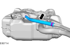
| | | 2 Inspect the recirculation hose routing to make sure that the top of the hose is not lower than the valve on the fuel tank. | | | Is the recirculation hose correctly routed? Yes Vehicles with fuel fired booster heater GO to A7. Vehicles without fuel fired booster heater GO to A8. No INSTALL the recirculation hose correctly. Test the system for normal operation. | | A7: CHECK THE ORIENTATION OF THE FUEL FIRED BOOSTER HEATER PORT (IF EQUIPPED) | | | 1 Remove the fuel tank.
REFER to: Fuel Tank - 1.6L Duratec-16V (Sigma)/1.6L Duratec-16V Ti-VCT (Sigma)/1.8L Duratec-HE (MI4)/2.0L Duratec-HE (MI4) (310-01, Removal and Installation) /
Fuel Tank - 1.6L Duratorq-TDCi (DV) Diesel/2.0L Duratorq-TDCi (DW) Diesel, Vehicles With: Fuel Additive Tank (310-01, Removal and Installation) /
Fuel Tank - 1.6L Duratorq-TDCi (DV) Diesel/2.0L Duratorq-TDCi (DW) Diesel, Vehicles Without: Fuel Additive Tank (310-01, Removal and Installation).
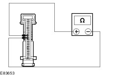
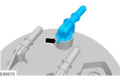
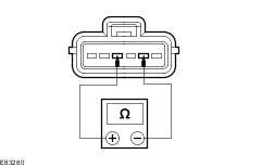
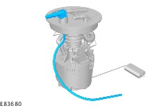
| | | 2 Check that the fuel fired booster heater port locating pin is correctly located into the slot. | | | Is the fuel fired booster heater port correctly installed? Yes No INSTALL the fuel fired booster heater port correctly. Test the system for normal operation. | | A8: TEST THE OPERATION OF THE FUEL PUMP AND SENDER UNIT/FUEL LEVEL SENSOR | | | 1 Measure the resistance between the fuel pump and sender unit/fuel level sensor C732 pin 2, component side and pin 4, component side with the fuel tank upright on a level surface and with the fuel tank inverted on a level surface. | | | Is the resistance between 200 Ohms and 206 Ohms with the fuel tank in the upright position and between 7.7 Ohms and 9.3 Ohms in the inverted position? Yes INSTALL the fuel tank.
REFER to: Fuel Tank - 1.6L Duratec-16V (Sigma)/1.6L Duratec-16V Ti-VCT (Sigma)/1.8L Duratec-HE (MI4)/2.0L Duratec-HE (MI4) (310-01, Removal and Installation) /
Fuel Tank - 1.6L Duratorq-TDCi (DV) Diesel/2.0L Duratorq-TDCi (DW) Diesel, Vehicles With: Fuel Additive Tank (310-01, Removal and Installation) /
Fuel Tank - 1.6L Duratorq-TDCi (DV) Diesel/2.0L Duratorq-TDCi (DW) Diesel, Vehicles Without: Fuel Additive Tank (310-01, Removal and Installation).
Test the system for normal operation. No | | A9: FLOAT ARM OBSTRUCTED OR COLLISION BETWEEN THE FUEL FIRED BOOSTER HEATER PIPE (IF EQUIPPED) AND THE FLOAT ARM. | | | 1 Remove the fuel pump and sender unit/fuel level sensor. | | | 2 Check whether the fuel fired booster heater pipe (if equipped) or any foreign material is obstructing the float arm. | | | 3 Check for any foreign material or obstruction that prevents the float arm from moving correctly. | | | Is there any sign of foreign material or causes of obstruction? Yes REMOVE the foreign material or the cause of the obstruction. Test the system for normal operation. No | | A10: TEST THE OPERATION OF THE FUEL PUMP AND SENDER UNIT/FUEL LEVEL SENSOR | | | 1 Measure the resistance between the fuel pump and sender unit/fuel level sensor C732 pin 2, component side and pin 4, component side with the float arm at the empty and the full positions. | | | Is the resistance between 200 Ohms and 206 Ohms with the float in the empty position and between 7.7 Ohms and 9.3 Ohms in the full position? Yes INSTALL the original fuel pump and sender unit/fuel level sensor. Test the system for normal operation. No INSTALL a new fuel level resistor card.
REFER to: Fuel Level Resistor Card (310-01, Removal and Installation).
Test the system for normal operation. | | PINPOINT TEST B : FUEL GAUGE SHOWS EMPTY EVEN WHEN REFILLED | | TEST CONDITIONS | DETAILS/RESULTS/ACTIONS | | B1: CHECK THE OPERATION OF THE FUEL GAUGE POINTER | | | NOTE:The fuel gauge pointer should move smoothly from empty to full in 2.5 seconds. At the maximum full position, the fuel gauge pointer must be on the full mark and not below it. 1 Carry out the instrument cluster Self-Diagnostic Mode. | | | Does the fuel gauge pointer operate correctly? Yes No REFER to the WDS. SELECT Guided Diagnostic/Body/Instrument Panel and Console/Instrument Cluster/Fuel Gauge and follow the instructions on the display. | | B2: CHECK THE INSTRUMENT CLUSTER FOR OPEN CIRCUIT DTC | | | 1 Using the WDS, check for DTC B1202 or carry out the instrument cluster Self-Diagnostic Mode and check for DTC 9202. | | | Is DTC B1202 or DTC 9202 displayed? Yes No | | B3: CHECK THE INSTRUMENT CLUSTER WIRING FOR OPEN CIRCUIT | | | 1 Remove the instrument cluster.
REFER to: Instrument Cluster (413-01 Instrument Cluster, Removal and Installation).
| | | 2 Measure the resistance between the instrument cluster C809 pin 8, circuit 8-GA7 (WH/RD), harness side and pin 7, circuit 9-GA7 (BN/RD), harness side. | | | Is the resistance greater than 218 Ohms? Yes No CHECK the electrical connector for corrosion and a secure connection, if OK, REFER to the WDS. SELECT Guided Diagnostic/Body/Instrument Panel and Console/Instrument Cluster/Fuel Gauge and follow the instructions on the display. | | B4: TEST THE OPERATION OF THE FUEL PUMP AND SENDER UNIT/FUEL LEVEL SENSOR | | | 1 Remove the fuel tank.
REFER to: Fuel Tank - 1.6L Duratec-16V (Sigma)/1.6L Duratec-16V Ti-VCT (Sigma)/1.8L Duratec-HE (MI4)/2.0L Duratec-HE (MI4) (310-01, Removal and Installation) /
Fuel Tank - 1.6L Duratorq-TDCi (DV) Diesel/2.0L Duratorq-TDCi (DW) Diesel, Vehicles With: Fuel Additive Tank (310-01, Removal and Installation) /
Fuel Tank - 1.6L Duratorq-TDCi (DV) Diesel/2.0L Duratorq-TDCi (DW) Diesel, Vehicles Without: Fuel Additive Tank (310-01, Removal and Installation).
| | | 2 Measure the resistance between the fuel pump and sender unit/fuel level sensor C732 pin 2, component side and pin 4, component side with the float arm at the empty and the full positions. | | | Is the resistance greater than 218 Ohms? Yes INSTALL a new fuel level resistor card.
REFER to: Fuel Level Resistor Card (310-01, Removal and Installation).
Test the system for normal operation. No | | B5: CHECK CIRCUITS 8-GA7 (WH/RD) AND 9-GA7 (BN/RD) FOR OPEN CIRCUIT | | | 1 Measure the resistance between the: - instrument cluster C809 pin 8, circuit 8-GA7 (WH/RD), harness side and the fuel pump and sender unit/fuel level sensor C732 pin 2, circuit 8-GA7 (WH/RD), harness side.
- instrument cluster C809 pin 7, circuit 9-GA7 (BN/RD), harness side and the fuel pump and sender unit/fuel level sensor C732 pin 4, circuit 9-GA7 (BN/RD), harness side.
| | | Are the resistances less than 1 Ohm? Yes No REPAIR circuit 8-GA7 (WH/RD) or circuit 9-GA7 (BN/RD) as necessary. Test the system for normal operation. | | B6: CHECK THE INSTRUMENT CLUSTER FOR SHORT CIRCUIT DTC | | | 1 Using the WDS, check for DTC B1202 or carry out the instrument cluster Self-Diagnostic Mode and check for DTC 9202. | | | Is DTC B1204 or DTC 9204 displayed? Yes No | | B7: CHECK THE FUEL GAUGE WIRING | | | 1 Remove the instrument cluster.
REFER to: Instrument Cluster (413-01 Instrument Cluster, Removal and Installation).
| | | 2 Measure the resistance between the instrument cluster C809 pin 8, circuit 8-GA7 (WH/RD), harness side and pin 7, circuit 9-GA7 (BN/RD), harness side. | | | Is the resistance less than 5 Ohms? Yes No REFER to the WDS. SELECT Guided Diagnostic/Body/Instrument Panel and Console/Instrument Cluster/Fuel Gauge and follow the instructions on the display. | | B8: TEST THE OPERATION OF THE FUEL PUMP AND SENDER UNIT/FUEL LEVEL SENSOR | | | 1 Measure the resistance between the fuel pump and sender unit/fuel level sensor C732 pin 2, component side and pin 4, component side. | | | Is the resistance less than 5 Ohms? Yes INSTALL a new fuel level resistor card.
REFER to: Fuel Level Resistor Card (310-01, Removal and Installation).
Test the system for normal operation. No | | B9: CHECK THE INSTRUMENT CLUSTER IS PROCESSING INPUT SIGNALS CORRECTLY | | | 1 Carry out the instrument cluster Self-Diagnostic Mode and scroll to the FUEL A/D and the FUEL PERCENT tests and note the readings. | | | Is the FUEL A/D greater than or equal to 181 with the pointer showing FULL?Is the FUEL PERCENT less than or equal to 08 with the pointer showing FULL? Yes Suspect fuel tank not filled correctly previously. Re-verify the customer complaint. No | | B10: FLOAT ARM OBSTRUCTED OR COLLISION BETWEEN THE FUEL FIRED BOOSTER HEATER PIPE (IF EQUIPPED) AND THE FLOAT ARM. | | | 1 Remove the fuel pump and sender unit/fuel level sensor. | | | 2 Check whether the fuel fired booster heater pipe (if equipped) or any foreign material is obstructing the float arm. | | | 3 Check for any foreign material or obstruction that prevents the float arm from moving correctly. | | | Is there any sign of foreign material or causes of obstruction? Yes REMOVE the foreign material or the cause of the obstruction. Test the system for normal operation. No INSTALL a new fuel level resistor card.
REFER to: Fuel Level Resistor Card (310-01, Removal and Installation).
Test the system for normal operation. | | PINPOINT TEST C : FUEL GAUGE SHOWS 1/4, ½ OR IS STUCK AT A SPECIFIC POSITION | | TEST CONDITIONS | DETAILS/RESULTS/ACTIONS | | C1: CHECK THE OPERATION OF THE FUEL GAUGE POINTER | | | NOTE:The fuel gauge pointer should move smoothly from empty to full in 2.5 seconds. At the maximum full position, the fuel gauge pointer must be on the full mark and not below it. 1 Carry out the instrument cluster Self-Diagnostic Mode. | | | Does the fuel gauge pointer operate correctly? Yes Vehicles with fuel fired booster heater, GO to C2. Vehicles without fuel fired booster heater, GO to C3. No REFER to the WDS. SELECT Guided Diagnostic/Body/Instrument Panel and Console/Instrument Cluster/Fuel Gauge and follow the instructions on the display. | | C2: CHECK THE ORIENTATION OF THE FUEL FIRED BOOSTER HEATER PORT (IF EQUIPPED) | | | 1 Remove the fuel tank.
REFER to: Fuel Tank - 1.6L Duratec-16V (Sigma)/1.6L Duratec-16V Ti-VCT (Sigma)/1.8L Duratec-HE (MI4)/2.0L Duratec-HE (MI4) (310-01, Removal and Installation) /
Fuel Tank - 1.6L Duratorq-TDCi (DV) Diesel/2.0L Duratorq-TDCi (DW) Diesel, Vehicles With: Fuel Additive Tank (310-01, Removal and Installation) /
Fuel Tank - 1.6L Duratorq-TDCi (DV) Diesel/2.0L Duratorq-TDCi (DW) Diesel, Vehicles Without: Fuel Additive Tank (310-01, Removal and Installation).
| | | 2 Check that the fuel fired booster heater port locating pin is correctly located into the slot. | | | Is the fuel fired booster heater port correctly installed? Yes No INSTALL the fuel fired booster heater port correctly. Test the system for normal operation. | | C3: TEST THE OPERATION OF THE FUEL PUMP AND SENDER UNIT/FUEL LEVEL SENSOR | | | 1 Remove the fuel tank.
REFER to: Fuel Tank - 1.6L Duratec-16V (Sigma)/1.6L Duratec-16V Ti-VCT (Sigma)/1.8L Duratec-HE (MI4)/2.0L Duratec-HE (MI4) (310-01, Removal and Installation) /
Fuel Tank - 1.6L Duratorq-TDCi (DV) Diesel/2.0L Duratorq-TDCi (DW) Diesel, Vehicles With: Fuel Additive Tank (310-01, Removal and Installation) /
Fuel Tank - 1.6L Duratorq-TDCi (DV) Diesel/2.0L Duratorq-TDCi (DW) Diesel, Vehicles Without: Fuel Additive Tank (310-01, Removal and Installation).
| | | 2 Measure the resistance between the fuel pump and sender unit/fuel level sensor C732 pin 2, component side and pin 4, component side with the fuel tank upright on a level surface and with the fuel tank inverted on a level surface. | | | Is the resistance between 200 Ohms and 206 Ohms with the fuel tank in the upright position and between 7.7 Ohms and 9.3 Ohms in the inverted position? Yes INSTALL the fuel tank.
REFER to: Fuel Tank - 1.6L Duratec-16V (Sigma)/1.6L Duratec-16V Ti-VCT (Sigma)/1.8L Duratec-HE (MI4)/2.0L Duratec-HE (MI4) (310-01, Removal and Installation) /
Fuel Tank - 1.6L Duratorq-TDCi (DV) Diesel/2.0L Duratorq-TDCi (DW) Diesel, Vehicles With: Fuel Additive Tank (310-01, Removal and Installation) /
Fuel Tank - 1.6L Duratorq-TDCi (DV) Diesel/2.0L Duratorq-TDCi (DW) Diesel, Vehicles Without: Fuel Additive Tank (310-01, Removal and Installation).
Test the system for normal operation. No | | C4: FLOAT ARM OBSTRUCTED OR COLLISION BETWEEN THE FUEL FIRED BOOSTER HEATER PIPE (IF EQUIPPED) AND THE FLOAT ARM. | | | 1 Remove the fuel pump and sender unit/fuel level sensor. | | | 2 Check whether the fuel fired booster heater pipe (if equipped) or any foreign material is obstructing the float arm. | | | 3 Check for any foreign material or obstruction that prevents the float arm from moving correctly. | | | Is there any sign of foreign material or causes of obstruction? Yes REMOVE the foreign material or the cause of the obstruction. Test the system for normal operation. No INSTALL a new fuel level resistor card.
REFER to: Fuel Level Resistor Card (310-01, Removal and Installation).
Test the system for normal operation. | | PINPOINT TEST D : FUEL GAUGE POINTER DELAYED IN MOVING UP WHEN THE FUEL TANK IS REFILLED | | TEST CONDITIONS | DETAILS/RESULTS/ACTIONS | | D1: CHECK THE OPERATION OF THE FUEL GAUGE POINTER | | | NOTE:The fuel gauge pointer should move smoothly from empty to full in 2.5 seconds. At the maximum full position, the fuel gauge pointer must be on the full mark and not below it. 1 Carry out the instrument cluster Self-Diagnostic Mode. | | | Does the fuel gauge pointer operate correctly? Yes Vehicles with fuel fired booster heater, GO to D2. Vehicles without fuel fired booster heater, GO to D3. No REFER to the WDS. SELECT Guided Diagnostic/Body/Instrument Panel and Console/Instrument Cluster/Fuel Gauge and follow the instructions on the display. | | D2: CHECK THE ORIENTATION OF THE FUEL FIRED BOOSTER HEATER PORT (IF EQUIPPED) | | | 1 Remove the fuel tank.
REFER to: Fuel Tank - 1.6L Duratec-16V (Sigma)/1.6L Duratec-16V Ti-VCT (Sigma)/1.8L Duratec-HE (MI4)/2.0L Duratec-HE (MI4) (310-01, Removal and Installation) /
Fuel Tank - 1.6L Duratorq-TDCi (DV) Diesel/2.0L Duratorq-TDCi (DW) Diesel, Vehicles With: Fuel Additive Tank (310-01, Removal and Installation) /
Fuel Tank - 1.6L Duratorq-TDCi (DV) Diesel/2.0L Duratorq-TDCi (DW) Diesel, Vehicles Without: Fuel Additive Tank (310-01, Removal and Installation).
| | | 2 Check that the fuel fired booster heater port locating pin is correctly located into the slot. | | | Is the fuel fired booster heater port correctly installed? Yes No INSTALL the fuel fired booster heater port correctly. Test the system for normal operation. | | D3: TEST THE OPERATION OF THE FUEL PUMP AND SENDER UNIT/FUEL LEVEL SENSOR | | | 1 Remove the fuel tank.
REFER to: Fuel Tank - 1.6L Duratec-16V (Sigma)/1.6L Duratec-16V Ti-VCT (Sigma)/1.8L Duratec-HE (MI4)/2.0L Duratec-HE (MI4) (310-01, Removal and Installation) /
Fuel Tank - 1.6L Duratorq-TDCi (DV) Diesel/2.0L Duratorq-TDCi (DW) Diesel, Vehicles With: Fuel Additive Tank (310-01, Removal and Installation) /
Fuel Tank - 1.6L Duratorq-TDCi (DV) Diesel/2.0L Duratorq-TDCi (DW) Diesel, Vehicles Without: Fuel Additive Tank (310-01, Removal and Installation).
| | | 2 Measure the resistance between the fuel pump and sender unit/fuel level sensor C732 pin 2, component side and pin 4, component side with the fuel tank upright on a level surface and with the fuel tank inverted on a level surface. | | | Is the resistance between 200 Ohms and 206 Ohms with the fuel tank in the upright position and between 7.7 Ohms and 9.3 Ohms in the inverted position? Yes INSTALL the fuel tank.
REFER to: Fuel Tank - 1.6L Duratec-16V (Sigma)/1.6L Duratec-16V Ti-VCT (Sigma)/1.8L Duratec-HE (MI4)/2.0L Duratec-HE (MI4) (310-01, Removal and Installation) /
Fuel Tank - 1.6L Duratorq-TDCi (DV) Diesel/2.0L Duratorq-TDCi (DW) Diesel, Vehicles With: Fuel Additive Tank (310-01, Removal and Installation) /
Fuel Tank - 1.6L Duratorq-TDCi (DV) Diesel/2.0L Duratorq-TDCi (DW) Diesel, Vehicles Without: Fuel Additive Tank (310-01, Removal and Installation).
Test the system for normal operation. No | | D4: FLOAT ARM OBSTRUCTED OR COLLISION BETWEEN THE FUEL FIRED BOOSTER HEATER PIPE (IF EQUIPPED) AND THE FLOAT ARM. | | | 1 Remove the fuel pump and sender unit/fuel level sensor. | | | 2 Check whether the fuel fired booster heater pipe (if equipped) or any foreign material is obstructing the float arm. | | | 3 Check for any foreign material or obstruction that prevents the float arm from moving correctly. | | | Is there any sign of foreign material or causes of obstruction? Yes REMOVE the foreign material or the cause of the obstruction. Test the system for normal operation. No INSTALL a new fuel level resistor card.
REFER to: Fuel Level Resistor Card (310-01, Removal and Installation).
Test the system for normal operation. | | PINPOINT TEST E : FUEL GAUGE POINTER FLUCTUATES UP AND DOWN WHILE DRIVING ON STRAIGHT/FLAT ROADS | | TEST CONDITIONS | DETAILS/RESULTS/ACTIONS | | E1: CHECK THE OPERATION OF THE FUEL GAUGE POINTER | | | NOTE:The fuel gauge pointer should move smoothly from empty to full in 2.5 seconds. At the maximum full position, the fuel gauge pointer must be on the full mark and not below it. 1 Carry out the instrument cluster Self-Diagnostic Mode. | | | Does the fuel gauge pointer operate correctly? Yes Vehicles with fuel fired booster heater, GO to E2. Vehicles without fuel fired booster heater, GO to E3. No REFER to the WDS. SELECT Guided Diagnostic/Body/Instrument Panel and Console/Instrument Cluster/Fuel Gauge and follow the instructions on the display. | | E2: CHECK THE ORIENTATION OF THE FUEL FIRED BOOSTER HEATER PORT (IF EQUIPPED) | | | 1 Remove the fuel tank.
REFER to: Fuel Tank - 1.6L Duratec-16V (Sigma)/1.6L Duratec-16V Ti-VCT (Sigma)/1.8L Duratec-HE (MI4)/2.0L Duratec-HE (MI4) (310-01, Removal and Installation) /
Fuel Tank - 1.6L Duratorq-TDCi (DV) Diesel/2.0L Duratorq-TDCi (DW) Diesel, Vehicles With: Fuel Additive Tank (310-01, Removal and Installation) /
Fuel Tank - 1.6L Duratorq-TDCi (DV) Diesel/2.0L Duratorq-TDCi (DW) Diesel, Vehicles Without: Fuel Additive Tank (310-01, Removal and Installation).
| | | 2 Check that the fuel fired booster heater port locating pin is correctly located into the slot. | | | Is the fuel fired booster heater port correctly installed? Yes No INSTALL the fuel fired booster heater port correctly. Test the system for normal operation. | | E3: TEST THE OPERATION OF THE FUEL PUMP AND SENDER UNIT/FUEL LEVEL SENSOR | | | 1 Remove the fuel tank.
REFER to: Fuel Tank - 1.6L Duratec-16V (Sigma)/1.6L Duratec-16V Ti-VCT (Sigma)/1.8L Duratec-HE (MI4)/2.0L Duratec-HE (MI4) (310-01, Removal and Installation) /
Fuel Tank - 1.6L Duratorq-TDCi (DV) Diesel/2.0L Duratorq-TDCi (DW) Diesel, Vehicles With: Fuel Additive Tank (310-01, Removal and Installation) /
Fuel Tank - 1.6L Duratorq-TDCi (DV) Diesel/2.0L Duratorq-TDCi (DW) Diesel, Vehicles Without: Fuel Additive Tank (310-01, Removal and Installation).
| | | 2 Measure the resistance between the fuel pump and sender unit/fuel level sensor C732 pin 2, component side and pin 4, component side with the fuel tank upright on a level surface and with the fuel tank inverted on a level surface. | | | Is the resistance between 200 Ohms and 206 Ohms with the fuel tank in the upright position and between 7.7 Ohms and 9.3 Ohms in the inverted position? Yes INSTALL the fuel tank.
REFER to: Fuel Tank - 1.6L Duratec-16V (Sigma)/1.6L Duratec-16V Ti-VCT (Sigma)/1.8L Duratec-HE (MI4)/2.0L Duratec-HE (MI4) (310-01, Removal and Installation) /
Fuel Tank - 1.6L Duratorq-TDCi (DV) Diesel/2.0L Duratorq-TDCi (DW) Diesel, Vehicles With: Fuel Additive Tank (310-01, Removal and Installation) /
Fuel Tank - 1.6L Duratorq-TDCi (DV) Diesel/2.0L Duratorq-TDCi (DW) Diesel, Vehicles Without: Fuel Additive Tank (310-01, Removal and Installation).
Test the system for normal operation. No | | E4: FLOAT ARM OBSTRUCTED OR COLLISION BETWEEN THE FUEL FIRED BOOSTER HEATER PIPE (IF EQUIPPED) AND THE FLOAT ARM. | | | 1 Remove the fuel pump and sender unit/fuel level sensor. | | | 2 Check whether the fuel fired booster heater pipe (if equipped) or any foreign material is obstructing the float arm. | | | 3 Check for any foreign material or obstruction that prevents the float arm from moving correctly. | | | Is there any sign of foreign material or causes of obstruction? Yes REMOVE the foreign material or the cause of the obstruction. Test the system for normal operation. No INSTALL a new fuel level resistor card.
REFER to: Fuel Level Resistor Card (310-01, Removal and Installation).
Test the system for normal operation. | | PINPOINT TEST F : VEHICLE RUNS OUT OF FUEL BUT THE FUEL GAUGE INDICATES A QUANTITY OF FUEL LEFT IN THE FUEL TANK | | TEST CONDITIONS | DETAILS/RESULTS/ACTIONS | | F1: CHECK THE OPERATION OF THE FUEL GAUGE POINTER | | | NOTE:The fuel gauge pointer should move smoothly from empty to full in 2.5 seconds. At the maximum full position, the fuel gauge pointer must be on the full mark and not below it. 1 Carry out the instrument cluster Self-Diagnostic Mode. | | | Does the fuel gauge pointer operate correctly? Yes Vehicles with fuel fired booster heater, GO to F2. Vehicles without fuel fired booster heater, GO to F3. No REFER to the WDS. SELECT Guided Diagnostic/Body/Instrument Panel and Console/Instrument Cluster/Fuel Gauge and follow the instructions on the display. | | F2: CHECK THE ORIENTATION OF THE FUEL FIRED BOOSTER HEATER PORT (IF EQUIPPED) | | | 1 Remove the fuel tank.
REFER to: Fuel Tank - 1.6L Duratec-16V (Sigma)/1.6L Duratec-16V Ti-VCT (Sigma)/1.8L Duratec-HE (MI4)/2.0L Duratec-HE (MI4) (310-01, Removal and Installation) /
Fuel Tank - 1.6L Duratorq-TDCi (DV) Diesel/2.0L Duratorq-TDCi (DW) Diesel, Vehicles With: Fuel Additive Tank (310-01, Removal and Installation) /
Fuel Tank - 1.6L Duratorq-TDCi (DV) Diesel/2.0L Duratorq-TDCi (DW) Diesel, Vehicles Without: Fuel Additive Tank (310-01, Removal and Installation).
| | | 2 Check that the fuel fired booster heater port locating pin is correctly located into the slot. | | | Is the fuel fired booster heater port correctly installed? Yes No INSTALL the fuel fired booster heater port correctly. Test the system for normal operation. | | F3: TEST THE OPERATION OF THE FUEL PUMP AND SENDER UNIT/FUEL LEVEL SENSOR | | | 1 Remove the fuel tank.
REFER to: Fuel Tank - 1.6L Duratec-16V (Sigma)/1.6L Duratec-16V Ti-VCT (Sigma)/1.8L Duratec-HE (MI4)/2.0L Duratec-HE (MI4) (310-01, Removal and Installation) /
Fuel Tank - 1.6L Duratorq-TDCi (DV) Diesel/2.0L Duratorq-TDCi (DW) Diesel, Vehicles With: Fuel Additive Tank (310-01, Removal and Installation) /
Fuel Tank - 1.6L Duratorq-TDCi (DV) Diesel/2.0L Duratorq-TDCi (DW) Diesel, Vehicles Without: Fuel Additive Tank (310-01, Removal and Installation).
| | | 2 Measure the resistance between the fuel pump and sender unit/fuel level sensor C732 pin 2, component side and pin 4, component side with the fuel tank upright on a level surface and with the fuel tank inverted on a level surface. | | | Is the resistance between 200 Ohms and 206 Ohms with the fuel tank in the upright position and between 7.7 Ohms and 9.3 Ohms in the inverted position? Yes INSTALL the fuel tank.
REFER to: Fuel Tank - 1.6L Duratec-16V (Sigma)/1.6L Duratec-16V Ti-VCT (Sigma)/1.8L Duratec-HE (MI4)/2.0L Duratec-HE (MI4) (310-01, Removal and Installation) /
Fuel Tank - 1.6L Duratorq-TDCi (DV) Diesel/2.0L Duratorq-TDCi (DW) Diesel, Vehicles With: Fuel Additive Tank (310-01, Removal and Installation) /
Fuel Tank - 1.6L Duratorq-TDCi (DV) Diesel/2.0L Duratorq-TDCi (DW) Diesel, Vehicles Without: Fuel Additive Tank (310-01, Removal and Installation).
Test the system for normal operation. No | | F4: FLOAT ARM OBSTRUCTED OR COLLISION BETWEEN THE FUEL FIRED BOOSTER HEATER PIPE (IF EQUIPPED) AND THE FLOAT ARM. | | | 1 Remove the fuel pump and sender unit/fuel level sensor. | | | 2 Check whether the fuel fired booster heater pipe (if equipped) or any foreign material is obstructing the float arm. | | | 3 Check for any foreign material or obstruction that prevents the float arm from moving correctly. | | | Is there any sign of foreign material or causes of obstruction? Yes REMOVE the foreign material or the cause of the obstruction. Test the system for normal operation. No INSTALL a new fuel level resistor card.
REFER to: Fuel Level Resistor Card (310-01, Removal and Installation).
Test the system for normal operation. | Configuration of the Instrument Cluster The instrument cluster is a programmable module, which must be configured by selecting the Programmable Module Installation Routine on the WDS. NOTE:When the new instrument cluster has been configured with the odometer value, its configuration cannot be decreased or matched. A new configuration will result in an increase in the displayed odometer value by a minimum of two units. NOTE:The odometer value must be recorded from the original instrument cluster before removal. NOTE:If the odometer value cannot be obtained from the original instrument cluster (display failure) the customer should supply the approximate value. The following features will need to be configured when a new instrument cluster is installed: - Anti-lock Brake System (ABS)
- All wheel drive
- Keyless vehicle entry
- Electronic power assisted steering
- Trip computer
- Voice control
- Parking aid
- Belt minder
- Safety belt not fastened
- Right hand drive
- Overspeed warning
- Reverse warning
- Turbocharger boost pressure
- Speed control
- Auxiliary heater
- Suspension control
- Washer fluid sensor
- Navigation
- Fuel cap release
- Engine type
- Display language
In addition the new instrument cluster will require the original odometer value to be entered. After the installation and configuration of a new instrument cluster. The passive anti-theft system (PATS) will require programming by selecting the Security Access routine on the WDS. |