| PINPOINT TEST C : A SINGLE MIRROR DOES NOT FUNCTION WITH SWITCH LOGIC |
| TEST CONDITIONS | DETAILS/RESULTS/ACTIONS |
| C1: CHECK THE EXTERIOR MIRROR FUNCTIONS WITH SWITCH LOGIC |
| | 1 Ignition switch in position II. |
| | 2 OPERATE the exterior mirror control switch. |
| | Does the exterior mirror function with switch logic? Yes VERIFY the customer concern. No Driver exterior mirror UP/DOWN inoperative GO to C2. . Driver exterior mirror LEFT/RIGHT inoperative GO to C5. . Passenger exterior mirror UP/DOWN inoperative GO to C8. . Passenger exterior mirror LEFT/RIGHT inoperative GO to C11. . |
| C2: CHECK THE DRIVER EXTERIOR MIRROR UP/DOWN CIRCUIT |
NOTE:The circuit numbers and wiring colors change at splice S200. |
| | 1 Disconnect Driver Exterior Mirror C807. |
| | 2 Ignition switch in position II. |
| | 3 OPERATE the exterior mirror control switch to select the driver exterior mirror. |
| | 4 Measure the voltage between the driver exterior mirror C807 pin 2, circuit 34-AD7 (BU/RD), harness side and pin 1, circuit 32-AD6 (WH), harness side. - OPERATE the exterior mirror control switch UP and DOWN.
|
| | Is the voltage greater than 10 volts when the exterior mirror control switch is moved to the UP position and is the polarity reversed when moved to the DOWN position? Yes INSTALL a new exterior mirror. TEST the system for normal operation. No |
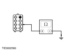
| C3: CHECK CIRCUIT 34-AD7 (BU/RD) FOR CONTINUITY |
| | 1 Ignition switch in position 0. |
| | 2 Disconnect Exterior Mirror Control Switch C741. |
| | 3 Measure the resistance between the exterior mirror control switch C741 pin 1, circuit 34-AD7 (BU/RD), harness side and the exterior mirror C807 pin 2, circuit 34-AD7 (BU/RD), harness side. |
| | Is the resistance less than 5 ohms? Yes No REPAIR circuit 34-AD7 (BU/RD). TEST the system for normal operation. |
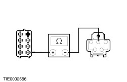
| C4: CHECK CIRCUIT 32-AD6 (WH) FOR CONTINUITY |
| | 1 Measure the resistance between the exterior mirror control switch C741 pin 3, circuit 32-AD1 (WH/RD), harness side and the exterior mirror C807 pin 1, circuit 32-AD6 (WH), harness side. |
| | Is the resistance less than 5 ohms? Yes INSTALL a new exterior mirror. TEST the system for normal operation. No REPAIR circuit 32-AD6 (WH). TEST the system for normal operation. |
| C5: CHECK THE DRIVER EXTERIOR MIRROR LEFT/RIGHT CIRCUIT |
NOTE:The circuit numbers and wiring colors change at splice S200 |
| | 1 Disconnect Driver Exterior Mirror C807. |
| | 2 Ignition switch in position II. |
| | 3 OPERATE the exterior mirror control switch to select the driver exterior mirror. |
| | 4 Measure the voltage between the exterior mirror C807 pin 3, circuit 33-AD8 (YE/BU), harness side and C807 pin 1, circuit 32-AD6 (WH), harness side. - OPERATE the exterior mirror control switch LEFT and RIGHT.
|
| | Is the voltage greater than 10 volts when the exterior mirror control switch is moved to the LEFT position and is the polarity reversed when moved to the RIGHT position? Yes INSTALL a new exterior mirror. TEST the system for normal operation. No |
| C6: CHECK CIRCUIT 33-AD8 (YE/BU) FOR CONTINUITY |
| | 1 Ignition switch in position 0. |
| | 2 Disconnect Exterior Mirror Control Switch C741. |
| | 3 Measure the resistance between the exterior mirror control switch C741 pin 7, circuit 33-AD8 (YE/BU), harness side and the exterior mirror C807 pin 3, circuit 33-AD8 (YE/BU), harness side. |
| | Is the resistance less than 5 ohms? Yes No REPAIR circuit 33-AD8 (YE/BU). TEST the system for normal operation. |
| C7: CHECK CIRCUIT 32-AD6 (WH) FOR CONTINUITY |
| | 1 Measure the resistance between the exterior mirror control switch C741 pin 3, circuit 32-AD1 (WH/RD), harness side and the mirror C807 pin 1, circuit 32-AD6 (WH), harness side. |
| | Is the resistance less than 5 ohms? Yes INSTALL a new exterior mirror. TEST the system for normal operation. No REPAIR circuit 32-AD6 (WH). TEST the system for normal operation. |
| C8: CHECK THE PASSENGER MIRROR UP/DOWN CIRCUIT |
NOTE:The circuit numbers and wiring colors change at splice S200. |
| | 1 Disconnect Passenger Exterior Mirror C808. |
| | 2 Ignition switch in position II. |
| | 3 Measure the voltage between the exterior mirror C808 pin 2, circuit 34-AD10 (BU/YE), harness side and C808 pin 1, circuit 32-AD9 (WH/GN), harness side. - OPERATE the exterior mirror control switch UP and DOWN.
|
| | Is the voltage greater than 10 volts when the exterior mirror control switch is moved to the UP position and is the polarity reversed when moved to the DOWN position? Yes INSTALL a new exterior mirror. TEST the system for normal operation. No |
| C9: CHECK CIRCUIT 34-AD10 (BU/YE) FOR CONTINUITY |
| | 1 Ignition switch in position 0. |
| | 2 Disconnect Exterior Mirror Control Switch C741. |
| | 3 Measure the resistance between the exterior mirror control switch C741 pin 2, circuit 34-AD10 (BU/YE), harness side and exterior mirror C808 pin 2, circuit 34-AD10 (BU/YE), harness side. |
| | Is the resistance less than 5 ohms? Yes No REPAIR circuit 34-AD10 (BU/YE). TEST the system for normal operation. |
| C10: CHECK CIRCUIT 32-AD9 (WH/GN) FOR CONTINUITY |
| | 1 Measure the resistance between the exterior mirror control switch C741 pin 3, circuit 32-AD1 (WH/RD), harness side and the exterior mirror C808 pin 1, circuit 32-AD9 (WH/GN), harness side. |
| | Is the resistance less than 5 ohms? Yes INSTALL a new mirror. TEST the system for normal operation. No REPAIR circuit 32-AD9 (WH/GN). TEST the system for normal operation. |
| C11: CHECK THE PASSENGER EXTERIOR MIRROR LEFT/RIGHT CIRCUIT |
NOTE:The circuit numbers and wiring colors change at splice S200 |
| | 1 Disconnect Passenger Mirror C808. |
| | 2 Ignition switch in position II. |
| | 3 Measure the voltage between the exterior mirror C808 pin 3, circuit 33-AD11 (YE/VT), harness side and C808 pin 1, circuit 32-AD9 (WH/GN), harness side. - OPERATE the exterior mirror control switch LEFT and RIGHT.
|
| | Is the voltage greater than 10 volts when the exterior mirror control switch is moved to the LEFT position and is the polarity reversed when moved to the RIGHT position. Yes INSTALL a new exterior mirror. TEST the system for normal operation. No |
| C12: CHECK CIRCUIT 33-AD11 (YE/VT) FOR CONTINUITY |
| | 1 Ignition switch in position 0. |
| | 2 Disconnect Exterior Mirror Control Switch C741. |
| | 3 Measure the resistance between the exterior mirror control switch C741 pin 5, circuit 33-AD11 (YE/VT), harness side and the exterior mirror C808 pin 3, circuit 33-AD11 (YE/VT), harness side. |
| | Is the resistance less than 5 ohms? Yes No REPAIR circuit 33-AD11 (YE/VT). TEST the system for normal operation. |
| C13: CHECK CIRCUIT 32-AD9 (WH/GN) FOR CONTINUITY |
| | 1 Measure the resistance between the exterior mirror control switch C741 pin 3, circuit 32-AD1 (WH/RD), harness side and the exterior mirror C808 pin 1, circuit 32-AD9 (WH/GN), harness side. |
| | Is the resistance less than 5 ohms? Yes INSTALL a new exterior mirror. TEST the system for normal operation. No REPAIR circuit 32-AD9 (WH/RD). TEST the system for normal operation. |